Ham Radio didn't start with an Appliance Box. Real Hams Build their Rigs! Update 5-13-2023 (XYL is in Hospital)
Get link
Facebook
X
Pinterest
Email
Other Apps
Ham Radio used to be synonymous with home constructed radios!
This Project will soon be winding down!
Listen to N6QW and his daughter Gina, discuss the music business. An easy listen and an opportunity to hear Pete discuss a subject outside of ham radio. Yes, he is a genius!
No work being done on the 10M SSB right now as I spend a majority of my time at the Healthcare facilities attending to the care of the XYL.
Last night well into the early morning hours I was at the local ER with the wifey. I only regret that I didn't wear my beret as I found that to be the #1 Chick Magnet.
But there are some interesting tools to be found in the ER like the no touch thermometer. Then of course there is this jewel.
A unique Urine collection system!
This is the equivalent to having a vacuum pump placed between the holidays with deference to the YL who named one leg Christmas and the other New Year.
It may be a bit of time before the smoke clears but, is not solder smoke. It is the blur of my other life. I regret not being able to fully conclude this project. So close but just no time!
73's
Pete N6QW
Update 5-10-2023. Failed Tests!
We tested the new Bifilar Transformer using the FT-82-43 Core and there was no change in output. So that is not the magic pill although a very interesting exercise. If you wound 73 Turns of #26 on the FT-82-43 core that is equivalent to a 2.5 Millihenry Choke. So, if you have an old Boat Anchor in need of a RF Choke -- you now have a substitute.
One final thought occurred to me and that was just a simple series choke feeding the Drain without a concern for an impedance transformation (4:1).
Lower Plot is the Power Input and the Top Plot = Output
Of Note I loaded the input with a 50 Ohm resistor to ground to force a 50 Ohm termination and to add a bit to stability to the circuit. W7ZOI in SSDRA called these Band-Aids. The Delta Gain is 15 dB, but we still see only 2.5 Watts across R2. I made this test without a LPF so that eliminates the LPF as an issue of cutting off at too low of a frequency.
Now removing R3 and keeping all else the same we get slightly higher readings BUT the same relative 15dB change is observed.
Lower Plot = Input, Top Plot = Output
Thus, we have the same simulation data but in practice with the single winding choke the power output is forever locked at 2.5 Watts.
So far, we have looked at power being fed back into the source rail, core saturation with heating and now the feed method. The various simulations all provide the same result -- a 15dB gain at 28 MHz.
Once someone shared with me that LT Spice becomes inaccurate to voltage inputs that exceed one or two volts. I ran the single winding RF Choke feed simulation with only one volt input, and we see a 15dB gain. This suggests that using 9 Volts PTP as the source is valid.
We now must ask why there is such a huge difference between the simulation and the actual hardware. That leads us to the conclusion that the only constant in all of the changes that were made was the IRF510.
Thus, will changing out that device cure the low power output. We must always harken back to the long-standing known. The IRF510 is NOT a true RF Device and they have always been known to drop off the cliff after 20 Meters.
I have affirmed with friend N2CQR that in his uBitx that was reworked to the circuit constants derived by KB1GMX that he saw a vast improvement on 10M from about 0.5 watts to 4 watts output BUT that was for TWO IRF510s. Some uBitx users get more power output on 10M but have switched to a 24 VDC Drain Supply.
Using the RF Choke feed, you see almost a +2 dB increase (at 28.3 MHz) in the power output at 24 VDC. If we were to see 57 Volts PTP at the output that equates to 8.12 watts. If we saw 45 Volts PTP at the output that is 5.06 watts. Those 3 watts is about a 2 dB increase.
Maybe I am chasing a suggested output that is not achieved in practice.
73's
Pete N6QW
Update 5-09-2023. The Bifilar Core
So, yet another suggestion about the loss of power. Basically, were losing 1/2 the power predicted for our IRF510. Instead of 5 watts we are seeing 2.5 watts output.
My mind travels back to vacuum tube high power amplifiers and their tank circuits. It was not unusual to see 2 to 3 inch in diameter Air Dux coils for Kilowatt amp tank circuits for 80 and 40 Meters. But once you went beyond that it was 1/4 Inch copper tubing. Factors such as high circulating currents in the tank and the skin effect where the hot juice runs on the surface of the conductor not through it. The tank below is one I made for the 20Meter 3CPX1500A7 1.5 KW amp that I built.
The Air-Dux coils used for the lower bands would melt on 20M at 1.5 KW.
Thus, the suggestion I received was that the 1/2 the power loss is going up in heat in the FT-37-43 due to core saturation. Likely we have 0.75 amps flowing through that little core with 50% efficiency to get 5 watts output. I know when I had only a single turn of wire on there (0.35uH) that the core was HOT to the touch.
We do have some FT-82-43 cores which in essence are 2X the size of the FT-37-43. The Al value for this core is 470 and so the inductance of 7 turns (#20) is 23.03 Microhenry for each winding.
Thus, our plan is to install the new Bifilar transformer and re-run the tests. The input signal is 9 Volts PTP or slightly greater than 200 Milliwatts. If we could nudge 14 dB gain out of the IRF510 that would be 5 watts out.
The upper trace is the power output, and the lower trace is the input. At 28 MHz the spread is 15dB. (This is the LT Spice Simulation not as measured on hardware!)
Perhaps tomorrow we can run some tests. Basically, the input was the other half of the power is in heat due to the small core size and saturation of the core. Yet another possible avenue to chase down.
73's
Pete N6QW
Update 5-06-20023. The Choke?
One blog reader suggested my low power output from the IRF510 might be the RF choke in the power supply lead feeding the IRF510. That raises an interesting point that I never really evaluated.
So, what would that mean in terms of reduced output? I am not certain of that answer. The 8.75uH choke is 5 Turns on a FT-37-43 core and with a currently published Al value of 350 for that core the impedance at 28 MHz is near 1539 Ohms. Certainly not Zero and not megohms.
This led me to an LT Spice simulation where the signal source is the IRF510 and at 5 watts would be about 45 volts PTP I suggest the series impedance is 12.5 Ohms. This signal would hopefully go straight away to the output side of the Bifilar transformer and not fed back into the DC power supply. So, I guess what we are really looking at is some of the output leaking into the DC rail.
I simulated the load as being the DC rail with a 13.8 Volt source and close to 1.5 amps and with a bit of fudging called it 10 Ohms.
Next is a plot of the AC Signal being back fed into the DC Rail.
Back fed signal ~ Small -170dB at 28MHz
This plot shows the 0 dB crossing at 2.5 kHz.
At 5 Millihenry the Zero dB crossing is less than 1 kHz.
Thus, even with a simulation that may not be close to correct there is a conclusion that likely making the RF Choke bigger has some brute force appeal to keeping RF out of the DC rail. BTW 5 Millihenry at 28MHz looks like 880K of impedance. Another piece of evidence -- the signal at 28MHz is -225 dB down.
73's
Pete N6QW
Update 5-03-2023. Did you spot the error?
About 3 AM this morning after being only asleep for one hour following a sojourn to the ER for the XYL, my brain said something is amiss.
Essentially the way that the Bifilar inductors are shown they are actually two separate inductors simply connected in series. What is missing is the LT Spice directive that express the Coefficient of coupling between L2 and L3 and since they are tightly wound that number is inched close to 1. So that is an error in how they were represented and the resulting plot.
Note the k3 L2 L3 1
The Blue Line is the Input and the Green Output
Note the linear relationship between the input values and the output values. At 29 MHz the input value is about 6dB, and the output value is about 21dB for a net gain of 15 dB in the amplifier. The bias level is 4 VDC (read running hot).
While this looks pretty decent after the correction, I still don't see but about 2.5 Watts output. More work needed.
73's
Pete N6QW
Update 5-02-2023. Why is my IRF510 performing like a 29A and not a 44DD?
In my quest to find out why my IRF510 amp only produces about 2 watts (if you squint) which led me to LT Spice Simulations. Fortunately, the IRF510 is in the library so we have existing parameters.
This is the typical circuit which I have used mainly on 40M and for a few 20 Meter radios.
This circuit would work great on 75 Meters, but sucks on 10M. So now you ask what can be changed to shift the output frequency and give more output at a higher frequency. There are two (actually three) parameters but with the circuit itself, the Bias (to shift the operating point) and the Tank Inductance are the principal actors. The other parameter is the Drive level but outside of the circuit.
Next I changed the tank from 10 Bifilar turns to 3 Bifilar turns which shifts each inductor from 35uH to 3.15uH.
This change in inductance has shifted the needle to about 11 MHz but still not 10Meters.
This change to 2 turns has moved the plot to the 17M Band -- better but not 10Meters. Note also the plot is tending to flatten and not peak. We next got down to 1 turn Bifilar and the inductance now is 0.35uH.
Right move! I did change the input level to 10 Volts which is 250 Milliwatts which is the drive level coming out of my Driver stage. So, the trick is to change the tank inductance but also focus on getting the drive level up to 14 Volts PTP. [Increasing the Drive level keeps the plot about the same shape but likely results in a higher dB output.]
At 14 Volts PTP drive level we should see greater that 5 watts out of our IRF510. We should investigate the use of a type 43 Balun Core with One single Bifilar winding. The Bias was at 3.2 Volts DC.
Now we have not changed the bias level so let's leave the input at 14 Volts PTP and the winding a single turn but move the bias around. This moves the output to > 12dB with 3.7 VDC.
If you had 7 watts of output with 14 Volts PTP input that is only 11.5 dB of gain which says you likely have smoked the IRF510 with 3.7 VDC.
Now let's change the drive level to 12 Volts PTP which is 360 milliwatts and set the Bias for 3.7 VDC.
This plot shows about 11.5 dB of gain which for 360 milliwatts input is 5000 Milliwatts or 5 Watts!
Thus, our premise of the Inductance (0.35uH) and Bias (3.7 VDC) changes as well as upping the Drive level (360 Milliwatts) will make the IRF510 spit out more RF on 10 Meters (44DD size).
The simulation looks good now to replicate these results in the hardware.
73's
Pete N6QW
Update 5-01-2023. Project Update.
73's
Pete N6QW
Update 4-30-2023. The Low Pass Filter.
One of the best Low Pass Filter Designs comes from W3NQN and I believed published in QEX. The desirable feature of his design is that it addresses the dreaded second harmonic.
You can search for this on the internet or if too lazy drop me an email and I will send you a pdf. Oh, you will have to search QRZ.com, to get my email.
The capacitor values in the schematic are exact but W3NQN gives you standard value caps that come close. You will have to use T-50-6 cores and I will let you calculate the turns of wire based on the specified inductance values. Time to fly the nest!
Look at the 2nd harmonic null!
We are getting close to wrapping up this project, but my time is limited so the posts will be fewer and soon to stop.
Still wrestling with the Driver stage and how to get more than 2 watts out of the final. Yesterday I bypassed the radio and fed a signal into the Driver from my signal generator thus only having the Driver and Final in the loop. Even with 8 volts into the Driver the output hovered at 2 watts.
This now tells me that the IRF510 board may also be on the usual suspects list. BUT I did smoke a 50 Ohm 2-watt carbon resistor. (Four 220 Ohm 1/2 watt in parallel.)
This has been fun, but I doubt anyone would build one. That said much of the design approach is good for any band that you would use. Keep in mind buying expensive MCU's or encoders along with a Nano VNA or a Tiny SA will not substitute for the low-level nut and bolt analysis that is mandatory. I often see in emails to me a jump to the last page and the lost storyline of the middle pages.
73's
Pete N6QW
Update 4-29-2023. Tibal Knowledge as a Closing.
I am reflecting on the events of the last couple of days and can only say: There are no shortcuts to success! In making that statement I have some supporting information and some caution.
Let us take this project and the Band Pass Filter.
We have the simulation we have the plot, and we have the working hardware.
In an earlier incarnation of the 10M SSB we had the P3ST and there is a group.io which is trying to build that project and recently the subject has come up about the Band Pass Filter used for that project. Immediately some newbies went out and bought a Nano VNA and built the unit and had no clue about what they were seeing. The problem is that those folks never invested the time to understand the circuit. They did not get a plot that looks like the above simulation!
I specifically advised one person what his problem was, and his answer was well here is what the Nano VNA says.
Let me demonstrate what the issue was, and it was Capacitor C4. I know from doing this thousands of times that if C4 is too small you get a peaked response and too large a double humped curve.
This is the curve if you only had 1/10 of a pF for C4 . No Flat Band Pass!
Now lets us say we made C4 4pF. The Camels hump!
(Note I broadened the response to see the hump)
Next the question asked was how to find small capacitors and there were three answers supplied. The 1st is found in SSDRA where Hayward shows specifically in the Appendix on homebrewing BPF's how to make small capacitance values.
The next method is to series a small precision fixed cap with a trimmer -- it's the old product over the sum approach. Finally, the 3rd method is the gimmick.
The response then was I never built a gimmick, but it looks too floppy, and it would change capacitance value. The gimmick in the photo is made from solid copper insulated wire and is solidly fixed to the copper squares --it doesn't flop.
The huge clue is I never built one and the second clue is he ignored the information supplied. Since this guy is so wedded to his Nano VNA, he could have tried some different capacitance values and the looked at the plot --INSTEAD he chose to say Your Design Sucks!
The next issue deals with the Direct Conversion Receiver that appeared in SPRAT. A ham in an overseas country wanted to build the radio and started on the Arduino path. Well, he couldn't get the code to load - seems like he had an Arduino kicking around the junk box --unknown if it worked. After getting a working unit he found that the encoder skipped digits. Actually, it doesn't skip digits, but he bought a detent type encoder so that you may have to go one or two clicks beyond the next detent to get the next digit. I suggested he buy a non-detent and then while the angular rotation might be slightly different for each digit --there are no skipped digits.
Well, he ignored my suggestion and went out and bought a really expensive detent encoder. When he got the same result, he shifted his sights to a Mega 2560 MCU. The code wouldn't load as the Mega as it seems to like other pins for the interrupts other than Pins 2 and 3 for the interrupts. Once again, he ignored what I was suggesting. I told him get it working and then we can fix skipped digits as a friend who is on vacation said he had code to fix that issue with the detents which he will share when he returns.
In both these cases the individuals asked for help with projects I designed but then resort to moving ahead without having a clue what they are doing.
RTFM. The projects as presented work and don't start "easter egging" by adding test instruments and purchasing hardware that likely will not give a different result. Stick to basics and you do have to learn about the circuits. If the individual had bothered to install LT Spice, he would have seen immediately seen the effect of C4 and try building a gimmick before telling me it won't work.
My time is limited, and, in the past, I have tried my best to hand hold those who are trying to homebrew a rig. I no longer have the time or patience with those who want to shortcut to the end without doing what is required! So that leaves me with a couple of options with the first being to no longer publish my work. The second is to stop responding when it is obvious you have stopped listening -- after all you did ask for help!
73's
Pete N6QW
Update 4-28-2023. The Driver/RF Amp
In hopes of wrapping this up sooner rather than later, I resorted to stealing some boards from prior projects and thus I do have a Driver and Final.
This is my standard template for a Final Board, and it can take either the IRF510 or the RD06HHF1. The Driver was a spare board from the P3ST project, and it has a 2SC5706 device. The BFR106 steerable amp (Rx RF Amp, Tx Pre-Driver) can produce 3 Volts PTP on 28 MHz. The 2SC5706 at most is producing about 9 Volts PTP which is just north of 200 milliwatts. The IRF510 produces 2 watts. That is a 10 dB gain.
Two issues, as the Driver needs to produce 500 milliwatts and with 10dB gain on the IRF510 we should see 5 watts. BTW-- 5 watts has to show up as 44.72 Volts PTP across 50 Ohms which is a hair less than 5 watts. The second issue is that I don't understand how with 3 Volts PTP in we only get 9 Volts PTP out as that is less than 10dB gain and the simulation shows twice that value in the 20dB range.
The two watts out is 28 Volts PTP across 50 Ohms. 28^2 = 784 and that value times 2.5 = 1960 milliwatts or 1.96 watts. So, OK you missed it as the 2.5 is a factor that converts to RMS and assumes a 5o Ohm load. [Hint: Take 1/2 PTP and multiply by .707 (RMS). Next square that value and divide by 50. Go ahead and do it and you will get 1.96 watts. Or use my method square the PTP and multiply by 2.5.]
The 2 watts looked clean on the scope but low to my expectations. We would need to see 14 Volts PTP from the driver stage for about 500 milliwatts.
While I was at it, I also scooped up an audio amplifier stage.
This long running posting will soon finish and will be made available on my N6QW website as a link to a word document. Thanks to those of you who had a stomach to ride along with me.
73's
Pete N6QW
Update 4-27-2023. Holding Pattern.
I am working on the Driver Amp and the Final Amp, so you won't see any updated posts for a few days. But I want to finish this jewel and hard to post while soldering. Likely the early part of next week we will have a final configuration to share. How appropriate ----
on or about May Day.
Another reason... my 1st contact on a newly acquired KWM-1 with VY2FU. Yes, I have more than one KWM-1, This was at 8:30 PM Local time tonight.
73's
Pete N6QW
Update 4-26-2023. White Noise Tests.
White Noise Tests (or Testes).
Does anyone give a crap beside me that we have a transceiver that is soon to be launched? No Virginia, it is not a Bitx Knockoff, it does not use TIA Amps and not even a hint of EMRFD nor a Facebook group. This is straight from the N6QW Newbury Park Laboratories!
73's
Pete N6QW
Update 4-24-2023. How the Homebrew 10M SSB Transceiver looks on an SDR Receiver.
,
I am anxious to get the other modules built so I can put a complete rig on 10M. So far, our design goal has been met! Here is the plan for the Driver Stage.
This is a spare PC Board from the P3ST project of two years ago and thus easy to install and test.
The key piece is the 8 pole QER Filter from K7TFC, www.mostlydiyrf.com. He also sells the BFR106, and the ADE-1 mounted on boards.
73's
Pete N6QW
Update 4-23-2023. Progress!
Yesterday I built and installed the Microphone amplifier stage using the BFR106 as the device.
10M SSB Transmitter Tests!
Microphone Amp Installed @ Upper Left Corner
73's
Pete N6QW
Update 4-22-2023.The Microphone Amp.
Yesterday we fixed the BFO issue and there is a link to a movie made after the fix. It sounds pretty natural. But the real test is how it sounds on transmit giving due attention to the transmitted band width and any hint of distortion or oscillation. The scope patterns and SDR waterfalls are unforgiving -- they show the signal, warts and all.
Now because the way I designed this rig and the way it was built, if I add the microphone amp circuit, wire in one relay and provide power on TR to five relays, we can look at the transmitter output. The most time-consuming event is the build of the Microphone Amp. I looked to use of the BFR106 as the Microphone Amp as I bought a stock of 25. I think I paid a quarter a piece. So, cheap enough!
Keep in mind that the Rx RF Amplifier seen in the video is simply steered to be the Tx Pre-Driver so we can sample the output of this stage and get a good deal of info of how the transmitter is performing. I plan to LOOK atthe transmitted signal on one of my commercial SDR transceivers. This will tell us much about the width of our transmitted signal.
Note in the real world R5, R7 and R8 are a 10K pot and the output is off the center wiper. The resistors let you see the level depending on where the pot is set.
If you make R1 about 220 Ohms, you will get a couple of more dB out of the amp. But there is plenty of gain!
The Fixed BFO
Final note the audio preamp stage ahead of the LM380N-8 will also be a BFR106 -- same circuit as the Microphone Amp. That makes 5 of the transistors in the 10M radio the BFR106. The other two discrete transistors will be the 2N2219A and the RD06HHF1.
73's
Pete N6QW
Update 4-21-2023. It is alive and well!
I jury rigged some boards and set up the main board for receiving. In short order, it was easy to tell wrong BFO frequency. To access more signal for assuring we had the right BFO Frequency, I temporarily moved the rig to 20M. Using a spare Arduino Si5351 I ginned up a variable VFO and used that for the main BFO to find the proper BFO frequency for USB. I did find that frequency and now I need to go back and refine the sketches and move the radio back to 10M.
I had to add some band-aides in the form of swamping resistors (ala W7ZOI) as the high gain of the BFR106 was a bit unsteady. I also built and am using the BFR106 Rx RF Amp/ Tx Pre-driver board. Much work still to be done as I then need to put the rig back on 10M. WYKSYCDS!
73's
Pete N6QW
Update 4-19-2023. More wiring added to the Main Board.
Main Board with the Added Wiring
Yesterday was most productive in that we worked on the Encoder/Display software and added enough wiring to run some initial Receiver tests. Board wiring included the two steering relays and the 5 VDC Three terminal voltage regulator. I also installed the audio filter ahead of the ADE-1 (left side).
There are some finger marks on the copper board, and I will give them an alcohol wipe down this morning. The only other work remaining on this board is the Microphone Amp and the wiring to the relay that switches between the Microphone Amp and the Audio Amp. But that is not needed for the receive tests.
The proof of the pudding will soon begin. Stay Tuned.
Pete N6QW
Update 4-18-2023. Transceiver Tuning with NO Encoder. The Magic and Genius of N6QW!
The Improved Software
One of the biggest problems with transceiver design is the limited Front Panel space. Lots of controls and big knobs soon creates a nightmare of how to fit it all in the real estate. So yesterday I spent some time with old sketches I developed for use with a keypad and presented herewith is an approach where a combination of a band switch and a tuning mechanism is rolled up into a small 4X3 Keypad matrix. It is perfectly OK to Ooh and Aw.
[After this video was made, I fixed some code issue and will post a subsequent video.]
Yesterday we superglued the relays to the main board, so we are close to running some receive only tests.
Hold on as progress is coming fast and furious so don't miss looking at the blog so you don't miss a critical advancement on the project.
BTW I even did this keypad approach with an 8X2 LCD and that really was a savings in panel space.
Mary Jo and Betty had their burgers and shakes -- on to the backseat of the 57 Volkswagen Beetle.
73's
Pete N6QW
Update 4-17-2023. More Hardware.
Yesterday I finally found the bag of relays I put away for safe keeping and it was so safe, I almost forgot where I stashed them. Today I will superglue the relays to the main board. I also milled the PC Board for the LO and BFO SMA connectors. You have to get a CNC Mill!
The Relays are DPDT so I can buss to either side of the relay and have access to either side. In essence I made a DPDT relay into a DPST. It offers a lot of convenience to do this and facilitates the wiring process albeit more expensive. But I got the relays on sale!
The two relays either side of the BFR106 amplifiers do the heavy steering so that the amplifier changes direction (although fixed in one direction) between Transmit and Receive. The pictorial below is both a wiring diagram and also shows how the signals pass only in one direction through the IF Module. Pure Genius Guys and Gals!
The relay on the left side toward the matrix of squares (upper left quadrant) is for the steering of the Microphone amp into the ADE-1 when it is used as the Balanced Modulator and to the outboard Audio amp when that same device is the Product Detector. The two squares just south of the microphone matrix are to facilitate the hookup of the external audio connections.
The two pads just north of the left side ADE-1 are the home of the AF LPF so that the audio signals hitting the filter are within the 2.8 kHz band pass. This is a good design practice -- limit the audio bandwidth.
Of "Note", there is no switching of the LO and BFO on receive or transmit. Look also at the BPF -- it is always connected to the same port on the Rx TX Mixer stage -- no internal switching the BPF on TR.
Finally, the relay in the back is for power switching (relays) between transmit and receive. Since the plan may be to feed the BFR106's with 5 VDC, I may need to add two more pads near the top middle of the main board for the 5V to the BFR106's. This regulator must be the regular 7805 (1 amp) three terminal regulator as the current draw is 300 Ma for the BFR106's.
[Now keep in mind -- this radio was not designed so that the minimum current draw would be 40 Ma on receive. It was designed for performance and likely will consume more than 40 Ma.]
A DFMA (Design For Manufacturing and Assembly) feature are the connections from the LO and BFO SMA connectors. I COULD have designed the board so that the trace to the edge connector was a continuous run. But instead, there is a break in the trace -- On Purpose! Connecting the trace from the SMA to the ADE is a small loop of wire and the purpose of the loop is so you can attach a scope probe to Pin 6 of either ADE-1 to observe the input signal. Now that is DFMA!
Mary Jo has been fed the usual Strawberry Shake and the Double Cheeseburger --so she is ready for the backseat of the 57 VW Beetle. When we enter Bob's Big Boy's Hamburger Joint at the Miracle Mile Mall in Monroeville -- they just know and automatically produce "the usual order". We are ready to Rock n' Roll!
73's
Pete N6QW
Update 4-15-2023. Amazing forward progress!
First to the IF Module where I did a bit of tweaking. Firstly, I do not trust Nano VNAs. I have two of them and neither produce repeatable results nor agree with each other. Secondly, I prefer alternate methods for looking at a filter pass band and that is what I did today.
I had done a look see at the QER Filter as installed in the IF Module about a week ago and had a few question marks about the pass band and the terminating impedance. So today I dug out my 1%, 137 Ohm SMD resistor and soldered that across the output of the filter ahead of the L Match and the 2nd IF Amplifier. This is the plot I got.
The plot was developed by taking PTP output readings every 100 Hz through the 'hot" IF Module. But First I did terminate the Filter output in 137 Ohms. The Voltage on the BFR106s, get this, was 5 Volts VDC. At 8 Volts you get twice the output and at 12 volts you get 3X. So, with 10 Millivolts in @ 12VDC you can see greater that 6 Volts out of the module. I am giving serious consideration to operating the IF Module at 5 VDC.
Once I had the PTP readings I divided the value by 10 millivolts (constant input) and then took the log of that times 20 (the voltage gain versus 10 for power gain). The vertical scale is in dB (derived from the output voltage and the input voltage) and the horizontal scale is frequency. The Center Frequency appears to be 4.915100 -- about 100 Hz lower than the nominal crystal values.
The BFO Frequencies would be 4913600 (LSB) and 4916600 (USB) and don't forget sideband reversal as the LO is above the operating frequency. The Band Width looks to be around 2800 Hz so I will have the HiFi sound and the QER Caps are all 33pF. After tests with a complete radio, I may add 10-15 pF across each crystal to shave off a bit of that SDR sound.
Next, I tackled building the Band Pass Filter. I found that I didn't have the T-50-6 cores but did have the T-30-6 cores. The adjusted schematic looks like this.
As usual R1 is for simulation purposes and is not installed in the BPF except for testing purposes.
Plot with T-30-6, Al = 36
SMD Cap Across the Output.
The BFR106 Amps
The 10Meter BPF
A Productive Day!
73's
Pete N6QW
Update 4-15-2023. Band Pass Filter
If you have been following the blog, you realize I have been wrestling with gain levels on the blocks.
At this point you can drive yourself nuts with various simulations. So, I think the game plan now is to add the Band Pass Filter and to jumper in the wiring for the receiver. This will enable us to test the IF Module on the air and then to tweak the gains accordingly as the only variable will be the IF Module.
We already have the LO and BFO board and I have a packaged utility audio amp board and a RF Amplifier board left over from the P3ST project. These pieces have fixed gains and are well characterized and thus my statement about the only unknown being the IF Module is indeed technically correct. This also lets us explore the overall systems gain. If we get the Receiver operating to peak performance, then many of the common circuits will perform the same on transmit.
Thank God for FT-8! I just tuned my KWM-1 on 20M and there are no signals (It is 5:15AM) except for FT-8 blaring away at 14.074 MHz. So indeed, we have on air signals to say yes, the radio is working. The same holds true for 10M-- I will hear FT-8 stations and nothing else.
While not covering the whole band this design will give a wide berth to my areas of interest, while enabling FT-8 and SSB. I will need to make a slight adjustment to the circuit values to slip down to 28.050 MHz as the bottom end. If you change C3 and C5 to 10pF, that does the job!
This is getting exciting. (Have you filed your income taxes yet?)
73's
Pete N6QW
Update 4-14-2023. Thinking Outside of the Box.
Aside from this being a cool looking box to house a homebrew rig, the box symbolizes that often we think of just what is inside the box. That can be a fatal error!
I have been so focused on getting the BFR106 into a design that the "lust for power output" has overtaken some real-world considerations that in effect lie outside the box.
Let us start with signal levels coming in from our antenna -- they may only be 1/2 a microvolt and to play on a crappy discrete part 2N3906/2N3904 homebrew audio amp at a couple of hundred milliwatts takes a lot of amplification. This is called the systems gain. To just get that 0.5 microvolt signal to 200 millivolts (200000 microvolts) takes 106dB of voltage gain. So, we need to think about that in our stage gain calculations.
I am now re-evaluating those calculations in terms of realistic module gains. We already saw that one of our initial IF Modules was 60 dB but perhaps wrongly thought we would see 5 millivolts as a signal input -- that is 5000 microvolts.
Essentially, we need to go back and look at the signal levels. The good news is that we are seeing substantive and stable gain from the BFR106 which is the really good news.
73's
Pete N6QW
Update 4-13-2023. Analysis - A Key to Open the Lock!
I am surprised that no one emailed me to say, "Don't Raise the Bridge, Lower the Water!" Instead of a 28 DB Pi Attenuator adjust the bias on the stages to provide a lower stage gain. Well, I think a combination of lower gain per stage and a smaller value attenuator to provide a constant load is the real answer. So that will be the next round of analysis.
Here is a design for the output stage with only 18 dB gain with a 250 Millivolt input would produce 2 Volts. I will add a 1 to 2 dB Attenuator and we can look at that design. The next piece is to redesign the 1st stage so that we only see about 250 - 350 millivolts into the filter.
However, the higher gain stage design with low signal input is ideal for the transmit chain to boost the signal coming out of the Transmit Mixer. So, the designs we have would be ideal for that purpose.
Notionally we may want no RF stage (to keep down the noise) and a really high gain stage following the transmit mixer. So now some more simulation. Just a back of the envelope calculation. If you had a 32dB gain stage (BFR106) with 15 Millivolts of input the output would be 600 millivolts. With a 20dB gain Driver stage (2N2219A) following the pre-Driver that would provide 6 volts of RF or about 90 milliwatts of drive to the final. Now we are on a path to finalizing a configuration and the gain levels. About 17 dB of gain in the final would be 5 watts. But experience says it would be better to have about 150 milliwatts of drive for 5 watts output or about 15 dB of gain.
Now back to the IF Module and the specifications for the ADE-1. According to the data sheet the ADE-1 is a 7 dBm device which means the LO drive should not exceed 1.414 Volts PTP of drive. The two other parameters listed are RF = 50 milliwatts and the IF has a max of 40 ma. I am uncertain of the RF parameter. But if we assume a load of 50 ohms and 40ma the E = 2 Volts. So, to be safe I would not put more than 1.5 volts PTP into the other ports.
Now a bit more data analysis. About a week ago after several months on the "Shame Shelf" and after switching to the PM2 Power Supply, my KWM-1 was working or at least the volume level and the S Meter were back working. I posted a YouTube video about that happy experience. That was short lived and back to low volume and no S Meter readings.
It was a ghost in the machine! It was a mystery as I tried the usual tube swaps and nothing and that then spelled out a component, like a capacitor or resistor. But where? Then an almost forgotten incident with a previously owned KWM-1. On that radio there was a problem in the IF stage wherein an IF transformer would not peak.
That transformer is L16. In tracking down the low volume and no S Meter wiggling, my thoughts went initially to the AGC circuit or a problem with RF being fed to the Receiver RF Amp stage -- never really looked at the IF stages. But had I really thought about it -- the AGC is driven by the signal from the IF stages --the classic AGC approach, (Duh!)
I attempted to peak L16 and no change in the audio or S Meter. I had a spare L16 from a junk KWM-1 I bought several years ago and so started there.
First things 1st! Since I now have a stock of 6BA6 tubes (15 recently purchased for $2.68) I cycled them through the V13 socket -- no change with any adjustment of L16. Now a word about how the KWM-1 is built. V13 and R56 are located towards the back of the chassis on the left side of the PA cage and L16 is toward the front right side of the chassis. Yes, circuit tracing is difficult! So disregarding sage advice from KB1GMX, I replaced a whole bunch of components at one time.
Starting 1st with the spare L16 can, I removed the coil from the can and replaced the 100pF postage stamp Mica with a new 5% Silver Mica. I also fed a 455 kHz Signal in series with the coil/cap and my DSO and peaked the core for 455 kHz. A very nice peak!
I did not have a 27pF Silver Mica to replace the 27pF Mica that was soldered across the terminals A and F, but used a 36pF 5% (a small retune of L16 would be OK). I also replaced the 510pF Mica with a 510pF 5% Silver Mica and also the 47K, 1/2 watt (that too was an issue in the prior KWM-1).
Back together and ... Loud Volume, S Meter Works as does the Internal Gain Pot. Man, I am a happy camper. This has been like a two-year sojourn without any sex, drugs or rock n' roll.
BTW, in the movie the dial shows 14.085 for FT-8. The 14.0 Crystal is off frequency as the 14.1 MHz and 14.2 MHz band slices are correct. That is a problem with 60-year-old crystals!
Both Mary Jo and Betty are smiling this morning!
73's
Pete N6QW
Update 4-12-2023. A Small Disaster!
In the above photo which was taken just after the crash of the BFR106s before the cleanup crew arrived to clean up the mess! We had to employ the Jaws of Life extraction tool (my micro-set of wire cutters) to remove the burnt-out hulks!
[I did not need to contact USAA for roadside assistance and because of my penchant for DFMA, new devices were in place in less than 10 minutes and the IF Module is back working as before.]
DO NOT APPLY 20VDC to the BRF106. So, ok my fat fingers got in the way of adjusting the variable DC Supply and there is a bad design approach on the variable supply.
The supply has coarse and fine adjustment knobs, and the issue is that as you try to sneak up on a value you may have reached the end of the travel of the fine knob and that requires a reset of the coarse knob. -- that may result in overshoot! It did! If you want to see this problem exactly look at the movie in the last post as I tried to set the value to 8 VDC. The Movie captures the problem.
So, my testing suggests a range of operating voltage of 5 to 15 VDC (Do not use 20 VDC!) Optimally the 8 VDC value suggests the safest and most reasonable approach. For those who lust for power, OK 10 VDC will be suitable.
Now a problem that I have never experienced previously -- too much gain and it is not oscillating. I am blown away by the gain levels that are possible. But as suggested in the movie dumping 5 Volts PTP into an ADE-1 input port will surely result in more smoked parts.
Some more data as I had not previously looked at the signal input "gag level". The video shows no more than about 6 millivolts and the output waveform was perfect. I moved that input to 15 millivolts and found at that level the output waveform began to distort.
Thusly we will need to look at what the signal level is going into the module and the level of signal coming out to the follow-on stage.
The INPUTS to the Module are from the Steerable Rx RF Amp on Receive and the Balanced Modulator on Transmit. Several things come to mind.
Because of the 60 dB gain of the IF Module, we would need very little if any RF Amplification ahead of the Module. Some designers say not more than 10 dB gain (some say 7dB max) from the RF Amp while some commercial radios had NO RF Amp stage (Atlas 180 and 210). Thus, that is one way of limiting signal input, on receive, is with no or little amplification ahead of the IF Module. That is not all bad as that improves the noise situation dramatically.
On the Transmit side the level of audio input to the ADE-1 Balanced Modulator would certainly limit the signal level input to the IF Module. Perhaps a gain limiting feedback amp in the microphone circuit. These two measures would indeed limit signal level inputs to the Module.
But what we need is real data on how much signal level is coming from the Balanced Modulator and how much from the RF Amp stages. Our P3ST transceiver would be a good source to answer those two questions. Need to set that up. We also need the max signal level permissible to the ADE-1 (not the LO level but signal level to the RF and IF Ports)
Now the real challenge is similar to getting Mary Jo's twin (Betty) into the backseat of the 57 VW Beetle. Perhaps, even on the same order of both at the same time. Yes, a huge challenge of what to do with all of that output gain. We are talking 5 Volts with a 5 Millivolt input! Certainly, dropping the supply voltage to 8 VDC dropped 3 dB off the total.
A more Brute Force Method would be as suggested by this LT Spice simulation. Yes, that is a 28DBPi Attenuator on the output side. There must be a lot of gulping --why have all of that gain only to attenuate it in the output? Indeed, a very good question.
There are some upsides to the Pi Attenuator with the first being dropping the signal level to something way less than 5 volts into an ADE-1. The other advantage is that the attenuator does provide a constant load to the IF Module especially since it is being "steered" between the RxTx Mixer and the Product Detector /Balanced Modulator. The actual value of attenuation required would have to be found based upon the input signal levels and the result from 57 dB of gain. Then it is math from thereon. Do not use a simple pot trimmer -- the Pi Attenuator looks like 50 Ohms Input and Output!
Bottom line -- we are now moving into more circuit development with a critical eye toward inter-circuit signal levels. A Convertible type 57 VW Beetle may also be an answer for a simultaneous twin encounter.
73's
Pete N6QW
Update 4-11-2023. IF Module Working!
Yesterday I did the final wiring on the IF Module and was pleased that no magic smoke was released! I am seeing gains in the 55-60 dB range with no hiccups, just as was predicted by the LT Spice Simulations.
First, I had to adjust the L Networks for 137.5 Ohms and as I found out you should run the BFR106's at 8 Volts versus 12 Volts. At 12 volts the output was warming up the 50 Ohm Load resistor. That would be too much RF into the ADE-1's.
The huge news -- the BFR106 devices indeed are very hot devices and worthy of inclusion in your next project. I was using drive levels around 1 to 5 Millivolts and seeing outputs up to 5 Volts PTP, that is 60 dB. [20*(log (5/.005))]
The output is CLEAN and as you adjust the input all you see is a CLEAN Sine Waves of Increased Amplitude. What a device and cheap too!
Undoubtedly the BFR106 will be used in the Steerable Amp stage that is the Rx RF Amp on Receive and the Tx Pre-Driver on Transmit. This is exciting.
Just like Mary Jo, the BFR106 is One Hot Mama!
73's
Pete N6QW
Update 4-10-2023. The 137.5 Ohm Fix.
Some detail of the MDRF Crystal Filter assembly. The three pads at each end can be fitted with an SMA connector but because of impedance mismatch use a wire to the Center Pin and a short direct connection to the Main Board Ground plane from either Outside Pad on each end.
Readily seen is the 10 Turn Bifilar matching transformer that results in a 4:1 match and with a Native 550 Ohms impedance that transforms to 137.5 Ohms for matching with the L networks.
There are some changes to the input and output modules (BFR106) to accommodate 137.5 Ohms that includes some capacitor and inductor changes along with two bias resistors. The completed rework would result in a Module of about 50 dB of gain. (Translated = 44DD versus a 29A.)
A point to be made if you are homebrewing a filter (a bad idea if you are a 1st time builder), very careful measurements must be made to ascertain the Native impedance and how that gets translated to 50 Ohms. The art of impedance transformations IS the Critical Path!
73's
Pete N6QW
Update 4-09-2023. Happy Easter to all of those who celebrate Easter. But a Good Excuse for anyone to eat lots of Candy!
Sometimes you are Wrong -- but it is the Genius who spots the problem before there is a Cataclysmic Event.
The issue is the Filter and how I originally made some assumptions about the Zin/out that are not correct. I was advised that the "Native Impedance" was 550 ohms and that a transformer on the board made it look like what I thought to be 250 Ohms (I am hearing voices these days) -- a 2:1 transformation. When I looked at the matching transformers, they were 10 Bifilar turns which would make that a 4:1 transform.
So now my L Networks must be redesigned so that there is a match to 137.5 ohms (550/4 = 137.5). So, the output of the 1st IF Amp must be looking at a 137.5 Ohm load and the input of the 2nd IF amp must appear as a 137.5 Ohm load to the Crystal Filter.
The mainboard must now have the L Networks modified and some of the bias resistors must also be tweaked.
The LT Spice Simulations have been modified to accommodate the load changes.
L3 and C2 have changed in Value and R4 Is changed.
About 28 dB of Gain at 4.9152MHz
The 2nd Amplifier Changes
C3 and L3 have changed as well as R3.
Output Amplifier Plot, about 27dB gain at 4.9152 MHz..
The import and power of data is ever so critical to a successful outcome. Mary Jo must be fed with a stop at Bob's Big Boy Hamburgers at the Miracle Mile Mall in Monroeville as a first step! (Just realized that is M^4.)
Have a Wonderful Day!
73's
Pete N6QW
Update 4-08-2023. Filter Mounted and the Fix of the Output Network.
Of note we fixed the Output network so there is a 100nF cap from the output L Network on the Input IF amplifier (left circuit). The Span was too great so we used a through hole cap but were the pads closer we would have used an SMD cap. The build is a mix of SMD and through hole components.
The filter board is mounted on 1/4-inch aluminum pillars and the three solder pads at each end are designed to use SMA connectors. Read Expensive! You can solder directly to the pads with the center pad being either input or output. the two outer pads are ground. The top and bottom sides of the board are a ground plane and are connected with the components that go to ground. The eyelets for the mounting screws are also connected to the ground plane. So even though there would be a mechanical connection, it would be wise to bring a ground wire from one of the outer pads soldered to the base copper main board.
A note about using the pads with coax. The point is mismatch as the Zin/out = 250 Ohms and the coax is 50 Ohms. SWR issues! Plain wire works FB and the way I laid out the amplifier outputs and inputs to the filter make for short wire connections to the board.
What may not be so obvious is that I installed a shield between the amplifiers which is just a scrap piece of PC board vertically mounted and soldered to the main board.
Moving along here. Mary Jo has been fed two burgers and her favorite strawberry milkshake. Let the fun begin.
73's
Pete N6QW
Update 04-07-2023. Progress on the Fabrication Front!
[Another day without any gift parts. The Goose who was laying Golden Eggs has moved on and shame on me for not asking for a Maserati earlier in the exchange.]
Much Progress on the Fabrication of the Main Board.
Yesterday was Good! I managed to get some serious soldering work done on the main Circuit Board.
History has shown that many of the blog readers study what I post in great detail. So, I have some detail to draw your keen attention forthwith and so you don't wonder there are two key points.
Firstly, the mounting holes for the 4.9152 MHz Crystal Filter align with the mounting holes in the main board. Bravo for measuring 400 times and cut once. The second point is that you cannot simply screw down the filter circuit board to the copper base plate. It must be elevated above the copper ground plane otherwise a Giant Short to ground!
For this photo and to show hole alignment I just placed the board on the ground plane -- see you can see the white holes of the top of the workbench. The normal install uses four aluminum spacers that are 1/4 inch tall to keep that physical separation. There also likely would be some capacitance coupling to ground if you simply placed an insulating sheet over the circuit board like plastic electrical tape and screwed her down. In the posting of 04-06-2023 you can see the aluminum spacers. Use the Spacers!!!!
Photographs and their value! I actually spotted something in the above photo, and it is an error in the build and initially in the LT Spice Simulation on the Output "L" Network. Yes, we are using matching with L Networks. See if you spotted the "goof up".
The Gain Plot of the amended Input circuit!
The Revised Circuit!
In the build (above photo) L3 Is connected to the output pad and not to Ground and C3 was not in the original simulation. Without C3 you essentially would have L3 shorting the input to Crystal Filter. A bit of trickery and the benefits of Capacitance in series. C3 is 100nF and C2 is 324pF. There is more than a Ten to One ratio between the two caps so that the series connection looks like C2. C3 prevents a dead short! For C2, I paralleled a 220PF and a 100pF to give 320pF. Close enough!
A bit of a test -- the LT Spice Simulation shows no difference with C3 in or out. BUT the Load of 250 Ohms is a resistor and not the filter input matching transformer. So, don't leave out C3 (like I almost did). Now R2 is strictly for simulation and not installed in the hardware fabrication.
Fixing what was originally installed is fairly easy. BUT if you had a bespoke circuit board made in Wuhan, Chine' you might have a problem with a fix.
Output from Filter Amplifier Circuit
Gain Plot from the 2nd Amplifier Stage.
We are on a roll here and of note much like with Mary Jo, we have just stopped at Bob's Big Boy Hamburger joint at the Miracle Mile Mall in Monroeville, PA. The fun is just beginning!
73's
Pete N6QW
Update 04-06-2023. Fabrication!
Firstly, the Magic parts shipments have ceased just short of the Maserati. Thus, today I started the Fabrication beginning with installing the Crystal Filter and the two BFR106's. I also will work on the Audio Amplifier board.
Installing the Crystal Filter is done more on the basis of "elbow room" and not damaging other parts. This is sort of a fit check and now the Crystal filter will be removed, and the other parts installed. The same applies to the BFR106's only in this case it is clearance and open space while you mount the SMD. Installing the BFR106's is like shooting a rifle --steady is the word while you hold your breath and hope you don't miss.
Once the BFR106's are installed the next in the sequence are the small SMD parts for each of the stages. Next would be the ADE-1's then the BPF and the Microphone Amp. The final pieces are the several relays which will be super glued to the board. The same applies for the Microphone Amp being done after the LM-380N-8. Oh, I use sockets for the LM380N-8 the machined pin kind.
Mounting the SMD does not involve Mary Jo.
73's
Pete N6QW
Update 04-03-2023. The Wish List.
First a very Happy Birthday to my favorite daughter (my only daughter). May you have a wonderful day!
Off the Shame Shelf. Wonders Never Cease!
Yesterday Amazon delivered the above box, another gift from the Anonymous Benefactor.
Of note on the Soldersmoke Podcast #245 I mentioned about receiving the gifts of parts like Three Terminal Voltage Regulators, a large stock of Zener Diodes, a box of 5% Resistors to which I said I could use some capacitors. Boom, look what shows up? Either I should have said nothing or maybe said a Maserati.
Nonetheless I am most appreciative of the kindness and generosity being shown. So, Thank You, Anonymous Benefactor! But there is a terrible guilt feeling about what is being spent to supply me parts. Of note I do have a very large junk box!
This is the week to start some soldering activities on the 10M SSB Transceiver, so stay tuned for progress photos. Keep checking K7TFC's Mostly DIY RF website https://www.mostlydiyrf.com. He has some things in the fire that will be very interesting to the ham homebrew community.
73's
Pete N6QW
Update 04-02-2023. Wanted!
I am on a quest to find some IF transformer cans that look similar to this. If you listened to the soldersmoke podcast #245 hosted by N2CQR, you heard me mention I bought fifteen 6BA6 vacuum tubes for $9 total shipped to me. They all tested good (or better). The plan after the 10M SSB is an all-vacuum tube 20M SSB Transceiver using 6BA6 tubes in every stage.
But the critical path items are the IF Transformer cans. I will wind the transformers and have the coil forms, but what I lack is the cans. So, please check your junk boxes and let me know what you have.
Again, to the Anonymous Benefactor who keeps sending me parts --- Thank You, as I really appreciate your kindness and generosity.
73's
Pete N6QW
Update 04-01-2023. The Benefactor.
Well, this is what arrived in today's mail.
Thank you, Anonymous Benefactor! If you are hard pressed on what to include should there be any future gifts: Consider 100nF 50 VDC ceramic caps and/or 4X6 inch by 1/16-inch-thick single sided copper PC board.
Again, thank you for your generosity.
73's
Pete N6QW
Update 3-31-2023. Hardware Stage!
Yesterday I spent some time with a bit of a puzzle. In the post the day before I showed the audio amplifier board from the P3ST where the pre-amp and amp were in a linear arrangement. This is optimum as it keeps the ins from the outs.
Then we have the practical side in that I am temporarily short of single sided copper vector board and have to order more. I looked in the scrap bin and found some small pieces. But none were large enough for a linear layout. So, then I thought about something unconventional where I took the two circuits (pre-amp and amp) and rearranged them on the board in a different fashion. The upper grid matrix is the pre-amp and the lower is the LM-380N-8 amplifier layout.
Between the two sections I left a bit of space to install a shield. So hopefully we have a means to address that eventuality of feedback and unwanted coupling.
The lesson is use what you have BUT think ahead that what you might change would give rise to other issues. Keep in mind power source bypassing and short direct leads with components. I think the post on hackaday today addresses this same issue -- but this is not the 1st time you heard it from me!
Huge caution -- it fits on the smaller footprint board but are we introducing conditions that would foster audio feedback. Plan ahead!
I know many of you are most anxious to see solder to the board and no more so than me personally. But keep in mind, first you do have to take Mary Jo to Bob's Big Boy Hamburger joint on the Miracle Mile in Monroeville before anything else can happen!
73's
Pete N6QW
Update 3-30-2023. Audio Amp Stage
This is our audio Amp Stage and is a repeat of what was used in the P3ST. I like this design because it uses the same circuitry for the Pre-amp as for the Microphone amp! That design has some great specs as we simulated that circuit in LT Spice.
The output stage the LM380N-8 uses but few external components and puts out room filling volume. The footprint is small too which makes for an easier integration into a box. Sure, you can fiddle with the discrete component amp stages but what you have is a lot of extra parts and far greater opportunities for screwing things up!
I like to think of the Audio Amp stage like the old Timex watch commercial where you "set and forget". This is sort of like, early in the evening, taking Mary Jo to Bob's Boy Hamburger joint at the Miracle Mile in Monroeville. You know the rest of the story -- set and forget!
73's
Pete N6QW
Update 3-29-2023. 10M SSB with 1/2 OLED
Above is a 1/2 Size OLED which could really cause you to squint. For those who want to make this a really small footprint.
73's
Pete N6QW
Update 3-28-2023. 10M SSB with the LCD.
One Digit At A Time
Yesterday was spent getting the LCD variant of the Arduino / Si5351 working for the 10M SSB Transceiver. The Pro-Mini Arduino is not suitable for use with the Color TFT as it lacks an on-board 3.3 VDC regulator. But for use with an LCD -- it is perfect. As you will see in the movie -- the Arduino/Si5351 is about the same size as the 16X2 LCD.
Of Note you would need an adapter to load code from a USB Port to the Pin header of the Pro-Mini. The item is called a USB to Serial Adapter
For less than $10 you can get two of them from Jeff Bezos. There is a trick to using these -- now I could charge you $10 (Via PayPal) to tell you the trick but if you send me an email -- FREE. Included in the FREE price is the details of the interconnect adapter cable. This is your lucky day! A Clue is the pinouts at the top of the Pro-Mini photo as these have to match the pinouts on the USB to serial Adapter. But you still don't know the special trick...
[Above are the Pro-Mini and the USB to Serial Adapter. Note the Inner-four pins with the labels GND, 5V, TXD and RXD. You must build a cable to connect the matching Pins and mark which end is which. This is not a straight wire pin to pin. But in essence the wiring crosses over. Just make sure you have the corresponding pin on each end mate with the corresponding pin on the other end. DO NOT Mix up the ENDs.
Mark the ends like you see PTP (Plug To Power) which means that end goes to the Adapter. The wires are color coded as I used Red for the +5, Black for the GND and Orange for SDA and Yellow for SCL. I use those same colors over and over. Any time I see an orange wire in one of my rigs I know it is carrying SDA signals!]
There are two photos of the outputs from CLK0 (LO) and CLK2 (BFO) which show unloaded the signal levels are too high for the ADE-1. In one case with 3.2 Volts PTP that is 14 dBm and the other is 2.2 Volts PTP which 10.8 dBm. So, I will add some pots to fine tune the output to 7 dBm. The frequencies as measured on the DSO show values in the proper range, but CLK2 where USB should be 4916700 Hz shows something higher. The Si5351 at this point has not been calibrated. -- right ballpark section --wrong row/seat.
I have worked out a matrix of frequencies that can be loaded into the code so that you can put this project on any band from 80- 10 Meters less 60 Meters. One regular Blog reader also named Pete, suggested this project should be called a Universal SSB transceiver as it could work on any of the ham bands (including 30, 17, and 12) and with close attention to unwanted mixing frequencies would indeed fill that role.
Now for those who are in desperate need of access to the 60M Band contact me at hamradiogenius@gmail.com as I have developed channelized code with one tunable channel.
My thoughts on focusing on the LCD 1st for the project is that it is less expensive and for first time "Arduweenie" users -- the code is simpler and easier to modify. Send me an email to the same above address if you want the code but it will be one day before I have it fully finalized.
Keep in mind the LCD code has two separate VFO's where the 2nd one boots up to the FT-8 frequency, and each has a VFO memory so switching from the SSB portion of the band to the FT-8 and then back -- you will not lose the original frequency. Slick is the operative word.
Think of the LCD option as Mary Jo on a park bench versus the backseat of the 57 VW Beetle!
We lost our fan from Puerto Rico but see two new additions from the Isle of Guernsey. There is a wonderful movie on Netflix about the Isle of Guernsey that was occupied by the Germans during WW II. Guernsey and Jersey islands are part of the Channel Islands off the Coast of Normandy.
Additional note, not far from me in SoCal are 7 islands known as the Channel Islands and the nearby town of Oxnard is known as the Gateway to the Channel Islands. There is even a university close by, Cal State University Channel Islands, which was formerly a Mental Hospital and supposedly the basis of the Eagles song Hotel California!
See you get exposed to more than just radio stuff!
73's
Pete N6QW
3-27-2023. An Addendum
If you have been riding along and are just about to pull the trigger, I want to share some critical points regarding the actual fabrication (that is upscale speak for build).
Aside from the usual errors of wrong part in the wrong place, reversal of leads on diodes and transistors, no connections or poor connections, shorts and solder bridges or simply cheap Chinese parts that were dead when you got them, we have a whole other category of miscreants. Read on to find out who they are!
You have the circuits working but you hear a terrible howl on receive or the pattern on the scope on transmit affirms --- OSCILLATION!
So, what causes oscillations? That question is similar to why are YL's cranky, moody, bitchy or downright nasty. There are no specific answers but there are pre-cursors that enable such conditions. [Our friend Mary Jo always had to have a full stomach. So never start any fun adventure with her without 1st stopping at Bob's Big Boy Hamburgers at the Monroeville Miracle Mile.]
There are parallels in our fabrications:
Circuit Layout and avoiding unwanted coupling of the output to the input.
Bypassing of the power rails. In some "rock solid" designs you often will see many bypass caps -- a 1nF, 10nF and perhaps a 100nF and even a 220uF. Essentially, they cover a wide spectrum of frequencies being bypassed.
Signal levels of the LO and/or BFO. This is why devices are rated for dBm drive levels. A 2 Volt PTP drive signal is 10dBm whereas a 1 Volt PTP drive signal is 4dBm. If you are using a DBM (Double Balanced Mixer) rated for 4 dBm and hit it with 2 Volts PTP --if you are lucky, it will oscillate otherwise you have a smoked part. For those who count on your fingers, a 1.414 Volt PTP signal is 7dBm. As always size matters! For the BTE's PTP = Peak to Peak Versus RMS (Root Mean Square). If you take the PTP value and square it and then multiply by 2.5 where next you take the log and multiply by 10 -- you have dBm. If you take the PTP Value and square it and multiply by 2.5 you have the power in milliwatts for a 50 Ohm load. The 2.5 is a conversion factor that converts to RMS and uses a 50-ohm load. Slick stuff. 10 Volts PTP across a 50 Ohm load = 250 milliwatts. 1 Volt PTP = 2.5 Milliwatts. [dBm is power levels compared to 1 milliwatt -- you must have milliwatts in the numerator!]
Lead Length is critical. Good Friend N2CQR and I, received an email from a new homebrewer who built an audio amplifier that oscillated. He also sent a photo! The circuit consisting of a transistor pre-amp and a packaged IC for the final was interconnected with a 10K pot that had three feet of wire for the interconnects. Well that 3 feet of wire was part of his feedback network. We told him to chop 2.6 feet of wire off the leads and run a test. Problem solved. Length does matter! This also applies to component lead length especially as you move up in frequency. Short direct connections are best!
Power Rail Noise coupled with inadequate bypassing. At times certain circuits will require some power source noise clean up. The LM317 adjustable voltage regulator does a good job of the cleanup. Ask the high-end audio guys about this problem. The other side of this is to avoid the cheap (WalWart) switching power supplies. Get a decent 12 Volt battery and use this to power circuits when doing the initial testing. This eliminates the cheap switching supplies from the equation.
The summary of the above, the fabrication requires great forethought and care in the process. Feeding her 1st helps too!
73's
Pete N6QW
Update 2-27-2023. The LCD Option.
In deference to those who feel intimidated with extensive code manipulation or are looking at not spending $23 for a display as this is a non-starter, we have a Budget Plan for you!
16X2 LCD Displays have long been a staple of ham homebrew construction. So today I hacked some old code so that the 10M SSB transceiver can be operated with a much simpler code set and with an inexpensive 16X2 display. I took one of my radios that had an LCD and an Arduino Pro-Mini and just loaded the code for this test and it works!
First and foremost, get a backlit display and also get the I2C backpack. The I2C backpack enables you to interconnect the 16 pin LCD with just four connections going to the Arduino.
Those same 4 connections go to the Si5351 as they are on a common buss. A code inside the sketch enables the signals that ride on the I2C to decode the data for the Display and ignore the Si5351 code set. K7TFC at Mostly DIY RF has an encoder that is also I2C so it can just plug into that same buss.
Here is a screen shot of the 16X2 LCD in the cool Juliano Blue color. Green is also nice. These LCD's can be found for around $5.
The code as such has an A / B VFO selection so that the start-ups are 28.3 MHz and 28.074 MHz. Just by flipping a panel switch you can listen if there is any activity on FT-8. Switch back and there is VFO memory, so you are back where you left off in the SSB band. I will make both code sets available.
This LCD code has a splash screen so you can extol your own genius abilities.
Think of the 16X2 LCD like a point a shoot camera. It is quick but the images are a bit grainy and fuzzy. Nonetheless it does give important information such as the Frequency, The Mode and the Step Tuning Rate.
It will not change your oil, nor put air in your tires. It is like Mary Jo on a park bench versus the backseat of the 57 VW Beetle.
73's
Pete N6QW
Update 3-26-2023. Introduction to the Arduino Code Set for the 10M SSB.
This is not the code for the 10M SSB! But it is intended to introduce the use of the ILI9341 with the CD4050 Level Shifter. This was the 1st Use of the ILI9341 on the Big Kahuna 20/40M SSB transceiver.
Definitely Not The Code!
Tone function now added back in 2/2/2017 USB BFO now 9001500
From N6QW using the 240 X 320 TFT Color display with the Si5351 Clock Generator.
The sketch includes selectable USB/LSB, a Tune function with 988 Hz tone and the
LO output. The sketch also includes a built in S Meter. Pete N6QW 1/18/2015
You must use the CD4050 Logic Level Convertor to make this display work
Arduino, CD 4050 Level Shifter, 240 X 320 Display WiringN6QW 1/2017
const int SW = 5; //selects upper or lower sideband
const int SW1 =12; // provides the TUNE fucntion
// STUFF ADDED HERE
const int MAXBANDS = 5; // the number of bands we are using
const int SWBAND[MAXBANDS]={A0,A1,A2,6,7}; // 80m on A0,40m on A1,20m on A2,15m on D6,10m on D7
const int_fast32_t rxfreqs[MAXBANDS]={12798500L,16198500L,23201680L,30300680,37400680}; // the default starting frequency for each band
int lastband=0; // used to keep track of the last band used
int backlight = 0;
int buttonState = 0;
int lastButtonState = 0;
Rotary r = Rotary(2,3); // sets the pins the rotary encoder uses. Must be interrupt pins.
void setup() {
int lp;
int pin;
Serial.begin(9600);
PCICR |= (1 << PCIE2);
PCMSK2 |= (1 << PCINT18) | (1 << PCINT19);
sei();
tft.begin(); // init display
Again, not THE Code but a code set!
73's
Pete, N6QW
Update 3-25-2023. The ILI9341 Display.
I guess because I spend a lot of time researching products for my projects that I often am set back when I get asked -- What Display? Yes, I know but you obviously don't.
Drumroll please, now is the time to meet the whopping 3.5-inch ILI9341 Based Color TFT. This is a big display but really makes a homebrew rig stand out and has the siren's call of use me in your radio. This display is around $23 from our friend Bezos. Follow the link below to get more details.
This is Big and a Hot Item! (No, we are not talking about Mary Jo!) I say this because the data display is in Color and has Large Print. The Pixels are 480X320 and so while there is a lot of real estate for the display, the actual Pixel count limits what you can display. I want to be able to read the Display from 10 feet away and no magnifying glasses are needed.
[There is an interesting new SSB radio from Indonesia being listed on eBay. The Price is $200. If it can deliver on the specs, then this might be quite the catch. BUT I was turned off as the display is a 1-inch square white OLED. In the same space they could have used a Color TFT like I did on my Peashooter Transceiver Project.]
For the install you need a 7-wire cable from the Arduino and the signal levels must be around 3.3 Volts. You cannot hook up the input pins to the Display directly to the Arduino output pins. You need to either have a resistive network or a level shifter but that is a small price to pay.
This is the wiring using the Resistors -- Same pins for a Nano!
For those of you who will take the diagram above and make these connections to an existing set up, you have several problems!
The 1st Problem is you will likely smoke your Display and/or the Arduino. If that doesn't happen, then most likely you will get nothing on your display and the reason is that the sketch must specify certain pins in the code and your code may not have those directions.
An additional failure point is the sketch must specify the ILI9341 as the display AND you must have the ILI9341 Library in the Library folder of your Arduino Directory. It is all those little details that ensnare those who rush in without thinking or knowing.
My sketches contain the hookup info as to what pins go to what pins and so you will have to read the info in the sketch and follow the directions. RTFM!
When all is Tickety Pooh, you should have something like this.
Finally,a Big Shout Out to the One (and only 1) Blog reader from Puerto Rico. Thank You for riding along.
From the blog statistics it is amazing to see the data generated. The 1st Shocker: A majority use Chrome with the last place to MSIE. Most of the viewers are from the US with the second largest group being the UK and of course our dear friend in Puerto Rico (Lest we forget he or she is in the US too). Thank you all for riding along.
73's
Pete N6QW
Update 3-24-2023. The Arduino Code
The Arduino Nano & Si5351
First before heading into the code, I wanted to describe a bit about the board above. This small assembly contains a 9 VDC regulator, the Nano, Si5351, Pin Headers and a resistor network to drop the 5 V signals from the Nano to 3.3 VDC for the Color TFT display. The resistors are easier to use than a level shifter like the CD4050.
Unique to this build is the mounting provisions for the board. The 1/2 inch angle stock enables a vertical mounting of the board to conserve precious internal space such as when you install it in a box. Not seen are the aluminum stand offs so that the board can be mounted horizontally. A bit of forethought gives you great latitude of how you "stuff a box".
I am still polishing the code so not totally ready for distribution. However, I will share some of the functional aspects of the code.
One of the most critical decisions is the frequency of the Crystal Filter as this causes three inputs into the code. I start by understanding that the Local Oscillator will be placed above the operating frequency. Thus, a SUBTRACTION (in a Mixer) of the Operating Frequency from the Local Oscillator (LO) will result in the IF (Crystal Frequency). Example an IF of 5 MHz would result from an LO of 33 MHz subtracting a 28 MHz operating frequency.
Placing the LO above has advantages for out of band signals, that are easily filtered out. Out of our mixer for the above case is 33 (LO) - 28 (Operating) = 5 (IF) and 33 (LO) + 28 (Operating) = 61. The sum product is way outside of our frequency schemes.
Thus, we will need to enter a start-up frequency of the LO. I picked 28.3 MHz as the DISPLAY startup and that display would be USB. By using a subtraction process the sidebands are inverted. Normally the sideband frequencies are found by adding/subtracting 1.5 kHz to the nominal center frequency of the filter.
For our filter at 4.9152 MHz the BFO frequencies are 4.913700 MHz and 4.916700 MHz respectively. Since we are subtracting the operating from the LO, a sideband inversion results and thusly, the 4.916700 is USB and the 4.913700 is LSB. So, to have 28.300 000 show up on the display with USB selected then the LO Start-up is 28.3 + 4.916700 = 33216700L. Data for values are input in Hertz and the L signifies LARGE.
So, the three entries are 33216700L for the LO, and 4913700L for LSB and 4916700 for USB. In the code we have a start-up and then in the code when the panel mounted switch selects USB or LSB the two BFO frequencies are injected into the calculation for the LO to be set and for what is to be displayed on the color TFT.
Now the code I will be supplying has some other functionality behind the panel that while not used for this rig is waiting in the wings. Five of the Arduino Pins are designated as digital inputs. by selecting these individual pins loads an LO number into the Arduino. I have set the numbers so that the start-up for 80/40 would be correct for LSB and for 20-10M the start-up would be correct for USB. For our 10 Meter SSB Rig only one number is loaded and that would be 33216700L.
By correct, does not mean anything is incorrect but if you have LSB selected then 3.8 MHz and 7.2 MHz would show up on the display when you switched to these bands. If USB is selected and you switched to the higher band then 14.2, 21.3 and 28.3 would show up on the display as the start-up. If the USB/LSB switch is on for the opposite sideband for that band -- the display would read 3.797 or 14.203 MHz at start-up.
Other bits of info jammed into the sketch is to set a range that the LO will tune. You can set it for 160 MHz or as I did for one sketch only 350 kHz. You also can set the step tuning range such as going from a 10 Hz step to a 1 MHz step.
I also include a TUNE function so that a 20 second pulsed 988 Hz tone is generated for tuning up an amp or adjusting a tuner.
You can have a splash screen at startup extolling only those with KNACK or inherent Genius could build this Radio.
Other functionality includes an S Meter display for you to see a wiggly line to show that the signal is indeed 5X9.
The Production Display Shown with FT-8
Now the disclaimer! I am not a software engineer or Coder so don't raise your expectations too high on my code development. I frequently get emails that my code is not elegant and that it is wasteful -- tight is right is the war cry. (Must be talking about Mary Jo?)
So, if you are one those then by all means write your own code. Will my code work -- Yes! Is it the best, NO!
So, if you are unhappy don't bitch at me and perhaps one of your radio illuminati buddies will write code for you.
73's
Pete N6QW
Update 3-23-2023. The Arduino/Si5351
But 1st Happy Birthday #3 Son, Nicolas.
This is a 1st Run of the Arduino, Display, and Si5351. I had this unit from the ill-fated wireless rig and decided to use it on this project. This is not the final display as the planned production unit is a 4-inch color TFT. No excuses you can't read the dial. As shown this is like a 3" display.
I have the comparable LO/BFO unit from Mostly DIY RF, but I would need to use what little precious time I have to build that module. So, this is a quick and dirty solution. I will have to think about the S Meter detection circuit, but the display will provide the capability to have a wiggling meter. When I polish up the code, I will make that available and just send me an email request. I will advise when it is ready.
Warm up the backseat of the 57 VW Beetle as Mary Jo is headed toward the car. BTW I think the Beetle had one of the best heaters. The defroster sucked as you had to have the VW actually moving for it to work.
An aberrant condition in SoCal. In the last two days we have had two tornados hit us. One was close by about 5 miles and the other in South LA actually did some serious damage to 10 buildings. I thought when I left St Louis -- all that was behind me.
Factoid: the St Louis area also is prone to earthquakes and one of the most severe (7.0) to hit the US was on the New Madrid Fault Line. It was so severe that Church bells in Boston were rung by the shock wave. It occurred at a time when Missouri was sparsely populated so not much damage there. (Late 1811 and early 1812)
73's
Pete N6QW
Update 3-22-2023. The Systems Gain in a Rig.
N2CQR & N6QW Preparing for a Podcast!
Collins 75A4, HT-32B and a Viking Linear Amplifier
Johnson KW Match Box and an Astatic Microphone.
A True Low Budget Station in the 1950-60's.
While I design some board layouts for the rest of the 10M SSB Radio, I thought I would spend some resources on evaluating the Systems Gain of the design. I thought this might be a good use of chatGPT. So, I asked about what is the standard for evaluating Systems Gain on a HF Radio Receiver. I used the receiver for the query based on the old wives' tale: If you can hear them, you can work them. Here is the answer I got.
The overall system gain of a high frequency radio receiver is typically expressed in decibels (dB) and is defined as the ratio of the power of the output signal to the power of the input signal. The standard gain for a high frequency radio receiver depends on the specific application and system requirements. However, in general, a high frequency radio receiver should have a gain that is sufficient to overcome any losses in the system, such as those caused by the antenna, transmission line, filters, and other components.
A typical system gain for a high frequency radio receiver can range from a few decibels to several tens of decibels, depending on the application. For example, a simple shortwave radio receiver might have a gain of around 10-20 dB, while a professional-grade HF communications receiver might have a gain of 50 dB or more. In some specialized applications, such as radio astronomy or deep-space communication, receivers may require even higher gains of several hundred or thousand dB.
It's important to note that the overall system gain of a radio receiver is not the only factor that determines its performance. Other factors such as sensitivity, selectivity, dynamic range, and noise figure also play an important role in determining the overall performance of a high frequency radio receiver.
In general, I have agreement with this answer but there are some hidden Gems in the response. The following is provided for your dining and dancing pleasure.
The Systems Gain is a ratio of the Power Output to the Power Input expressed in decibels (dB). That is good.
But in the last paragraph are the hidden Gems in that it speaks to Sensitivity, Selectivity, Dynamic Range and Noise Figure. If you are only able to DETECT very strong signals, you would get a very loud output with 100 dB of Systems Gain. But the hardware might miss the 0.05 Microvolt signal coming from afar. The 100 dB Systems Gain is important but with a weak front end even having large systems gain numbers-- you might not hear the weak signal and all the 100 dB is doing is amplifying the noise.
With some careful systems design it is a goal to have this project be more than a general-purpose short-wave receiver with a transmitter thrown in for good measure.
With a rough initial seat of the pants calculations our LT Spice Simulations tells us the following.
The BFR106 RF Amp = + 20 dB of Gain
The BPF = - 2 dB of Loss
The RxTx Mixer (ADE-1) = - 5dB Loss
IF Module = + 50dB Gain
Product Detector = - 5dB of Loss
Audio Amplifier = + 20 dB of Gain
Internal Circuit Loss = - 3 dB of Loss
So, if we did the math properly, we get a Systems Gain of 75 dB of gain. Which puts it in the range of Professional Grade. But we also want the radio to be sensitive at 30 MHz and the selectivity is driven by the 8 pole QER Filter.
The BFR106 RF Amp stage has two important jobs where we run it "hot" to insure good dynamic range and we run the gain level in that we amplify the signal and not amplify a lot of atmospheric noise in the process.
Some observations from radios of the past. I have a small collection of Boat Anchors and one of my most cherished is a Swan SW-120 made in Benson Arizona in 1961. (Read an early Swan radio literally hand made by Herb Johnson.) The SW-120 front panel has a control marked VOLUME. But it does not control the audio amplifier stage Volume but the Cathode Bias on the RF Amplifier Stage. Think Value Engineering, only one control and it really does control the Volume!
I also have a Swan 240, made later in 1963 and it has both a Volume Control and a RF Gain Control. Some 60 years later I find that the best sounding signals are heard with the RF gain control cranked back about 15 to 20%. With the RF Gain "Full Open" the background noise masks the normal signals. Likely in 1963 -- no one noticed.
The recent gift of the TR-7, a true marvel of Engineering, is telling on 15/10 Meters: She is a 29A and not a 44DD. This is not specific to my radio, but all TR-7's were this way. In a Panty Hose design (one size fits all) there often are compromises made such as balancing out the gain over 30 MHz. Too much of broad band gain on 10 Meters might overload the receiver on 75 and 40 Meters.
On my KWM-4 I have a panel mounted switch to reduce the gain by 10 dB on the lower bands as I opted for "hot rod" performance on the higher bands.
On paper the 10M SSB Rig Systems Gain looks good and the use of the BFR106 in the RF and IF stages employ a device that is good into the Microwave region and our LT Spice simulations show a flat gain (44DD not 29A) at 10 Meters.
You must conclude that building a radio from scratch involves a lot more than throwing a bunch of parts together and you will certainly learn more than just building a kit.
73's
Pete N6QW
Update 3-21-2023. More Fab Stuff!
Yesterday was highly productive and most of the pads on the mainboard were cut on the CNC Mill. The QER Filter also arrived. It was nice to see I accurately placed the location of the Crystal Filter on the Board (1.5 Inches from each side).
Locating parts/circuits on the board boils down to: When You Know Stuff You Can Do Stuff.
We are now at a point where we can start soldering parts to the board. But here is where experience tells you to also do a fit check of the relays that will be added as in the P3ST.
There will be four relays added to the main board and the one that may need some diddling as to location is the one between the Crystal Filter and the BPF (upper right-hand quadrant). I will move the relays around to find the best location for wiring access to the parts and circuits.
Using a 5mm Mechanical HB lead pencil, I will mark those relay locations and subsequently superglue the relays to the board dead bug style during the install sequence. They DO NOT get installed until later when much of the SMD soldering is done!
Because of the super small SMD parts, it is best to start with the inner-most circuits and work your way outwards. Translated for the BTE's this means you install the BFR106 amps 1st followed by the ADE-1's and then the Microphone Amp and BPF. The relays are installed after the Audio Filter.
The purpose of the Audio Filter is to limit the Band Width of the audio being supplied to the Balanced Modulator. Thus, the resultant DSB signal passed to the QER filter fits within the bandwidth of the Crystal Filter. Because of the value of the specific BFO frequency the sum and difference frequencies of the Audio & BFO, only one sideband passes through the Crystal Filter.
In one case the difference is below the Crystal Filter Bandwidth and in another case the sum is above the Crystal Filter Bandwidth. The steepness of the skirts and the flatness (no ripple) of the Passband makes a huge difference in how your signal sounds on the other end. It follows that limiting the audio frequency range ensures that the actual generated sideband has audio that fits with in the 2.7 kHz BW.
Let us share the details as I just know there are a few blank looks. Let us say we have a Center Frequency 9 MHz Filter and the BFO frequencies are 8.998500 MHz and 9.001500 MHz respectively. Now if we add audio to the 8.998500 BF that will fall within the bandwidth of the Crystal Filter that is centered on 9 MHz with a 2.7 kHz wide BW. That BFO frequency Minus the Audio will fall outside (below) the Filter Band Pass. With our 9.001500 MHz BFO the subtraction (difference) of the audio falls within the Crystal Filter Band Pass and the addition (sum) is outside the Band Pass. In Normal operation the 9.001500 MHz is Lower Sideband (LSB) and the 8.998500 MHz is Upper Sideband (USB).
In the case where the LO is placed above the working frequency and a subtraction result in the Receiver Mixer stage to reach the IF frequency, then we have Sideband Inversion. Now the 8.998500 MHz BFO decodes LSB, and the 9.001500 MHz BFO decodes USB.
Now the boards/modules from K7TFC are a bit larger than what you see on my main board which is 4X6 inches. To use Todd's Modules, (ADE-1 and BFR106) you will need a board about 8X12 inches. This is good for those who are new to homebrewing -- lots of space to work with the hardware. When you get more skilled (and buy a CNC Mill) you can use the bare devices.
Before I do any soldering, I have a few other circuit boards that I have to cut on the CNC mill including the Audio Amp (2N2222A + LM-380N-8), the BFR106 RF Amp/Tx Pre-Driver, the 2N2219 Driver stage and the RD06HHF1 Final Amp. I am opting to cut all of the boards now so then it will be a case of continuous soldering parts versus having to stop the soldering to make boards.
Are you excited? I sure am.
73's
Pete N6QW
Update 3-20-2023, Addendum.
When taking on a project like the 10M SSB transceiver, think beyond just building a single prototype as likely it will have many changes and improvements and that is where the subject of expendable parts arises.
The 1st completed radio may not look pristine but the second one will look like a museum piece. That also brings up building in modules. All of my projects are experimenter's platforms where making improvements is done in the modules and no need to destroy a whole radio just to improve the microphone amplifiers stage.
The "island square" CNC Milled pads approach also facilitates making changes as typically spare pads come with the layout. A parts specific layout is bad for those of us who like to fine tune our rigs.
Parts Procurement
When purchasing the small parts buy in quantity. The cost of buying 10 pieces versus 1 SMD 100nF cap really is peanuts. Now, costly parts like the Crystal Filter ---you only need one. The bulk purchase of the small stuff likely only adds about 5% to the total overall project cost, if that. The huge savings is in the shipping cost especially where fixed rates are involved. 1 piece or 10 pieces -- the shipping cost is the same! But to have to buy a 2nd piece because you bought only 1 cap -- you can see the math!
Update 3-20-2023. Start of Fabrication!
Today we started cutting the first pads for the BFR106 IF Amplifiers. This is a 1st run so after we start installing parts, we'll have a better idea if any adjustments are needed.
The cutting had to be done twice as the cutter moved further away from the start location some of the traces were only scratches and not full cuts. A way to fix this is to cut one pad and then move the cutter to a new location and set the depth to a little deeper cut. The 2X cutting caused some ragged edges which can be cleaned up.
There are a couple of shots showing the BFR106 on the pads -- they look like specs of dirt. This should work OK!
Some Clean-ups of the Burrs.
The Spacing between the pads. There will be a Shield Installed!
The further milling on the board will involve the two ADE-1's, the Microphone Amp stage, The Band Pass Filter, the Audio Filter and installation of the Steering relays. The QER Filter will mount on four standoffs, just above the pads shown.
73's
Pete N6QW
Update 3-19-2023. L Match Fine Tuning.
Wes Hayward, W7ZOI, cautioned about having too much gain in a single stage. He reasoned that two stable stages in cascade were a better approach to achieving a high stage gain output.
That rang in my head about 3AM this morning and I revisited the BFR106 Amplifier stage following the Crystal Filter. Thus, a bit of a tweak to have a stable module. As it stands now with the insertion loss of the filter (3 -4 dB), we still will see better than 50 dB of gain across the IF module.
This next week I hope to start fabrication of the main board. We are warming up the back seat of the 57 VW Beetle and we have some discount coupons for Bob's Big Boy Hamburger Joint. Mary Jo was no fun on an empty stomach!
73's
Pete N6QW
Update 3-18-2023. L Network Matching
My 4.9152 MHz filter I was advised has a Zin/out of 250 Ohms. So, this presents a design problem where the output of the 1st BFR106 Amp stage must present a 250 Ohm source to the input side of the Crystal Filter. Nominally the input to the 1st BFR106 is 50 Ohms from the Rx Mixer (ADE-1) or the Balanced Modulator (ADE-1).
The output from the Crystal Filter is 250 Ohms and thus we need a match from the Crystal Filter to the 2nd BFR106. Of course, the output of the BFR106 is set to 50 Ohms to match the Product Detector (ADE-1) or the Transmit Mixer (ADE-1).
We are in luck as W8DIZ has a calculator for all of his toroid cores (He is afterall the Toroid King.). This is where you pick the core add in the frequency and the match from what to what. Now I did find his values to be slightly off from what I calculated but as they say close enough.
NOTE: R2 is for simulation purposes and is not installed in the actual circuit. The difference from the calculator is the inductance value for the # of turns as I rounded it to 29 Turns versus his 27 Turns. His Inductance was 4.05uH.
For 500 mv input you get 28dB of Gain at the IF and so this L Network will be installed after the 1st IF amp, the BFR106.
Second IF Amp Zin = 250 Ohms
My input L Network match doesnot match the calculated W8DIZ values, but it does give a nice plot of gain. I trust the LT Spice and will use the values from the simulation. But caution with such a high gain, circuit layout and physical isolation as well as cranking back on the gain may be required. But this is a starting place.
Keep in mind the theoretical values are the rose-colored glasses and so be advised. No matter how much that one beer goggles, Mary Jo still weighs 250 pounds!
73's
Pete N6QW
A burning question! Who out there in radio land has some pet circuits for the 6BA6 vacuum tube? I needed a replacement 6BA6 for use in one of my "TooB" transceivers. So, I went to eBay and found for sale 15 pieces of "good 6BA6's ~ tested" for $8.96 including shipping.
So is it possible to build an entire SSB transceiver using nothing but the 6BA6 tubes. We know that the RF Amp Stage, the IF Amp Stage and the BFO and VFO can be the 6BA6 tubes.
Likely a Microphone Amp and the Audio Preamp can be the 6BA6 tubes. Certainly, mixer stages would be OK with the 6BA6 tubes. So that leaves us with the Balanced Modulator (maybe a diode ring), the Product Detector (perhaps another diode ring), the Transmit Mixer and the Driver stage. All look like they would work with the 6BA6. But the nuts to crack are the Audio Output Stage and the Final RF Amplifier stage.
Update 3-17-2023. Crystal Filter Matching!
My 4.9152 MHz Crystal Filter is on its way to me, and Todd was kind enough to supply some photos of his VNA measurements on my Filter.
But 1st some crystal filter musings. The mesh capacitors used in the filter set the band width. Smaller capacitors give wider band widths. Typically, something between 39 pF and 68 pF set a pretty good SSB band width. For narrow CW, 470pF is the choice.
Frequently you will see that crystal filters in the range of 4 to 12 MHz are the frequencies of choice. Some of that has to do with crystal stability. Often you will see that represented as 50 ppm. Translated a 12 MHz filter can have a frequency stability of +/- 600 Hz. (50X12). But if you got a hair up your butt because you saw a transceiver with a 24 MHz Filter that same 50 ppm is +/- 1.2 kHz. Lower is better!
So now you have a suitable band with for a SSB Filter but that is only 1/2 solution. Ideally the top of the plot should be flat and the variable that describes that flatness is "ripple". Filters with a lot of ripples are to be avoided. The ripple factor is determined almost exclusively by the matching transformers and the proper termination of the filter. Basically, filters with a high degrees of ripple pass signals at different signal levels thru the pass band and that leads to distortion and awful sounding signals.
Two parts: 1) Matching and 2) Proper Termination.
In building a homebrew filter it is a crap shoot and often you must "twizzle" the matching transformers to have minimum ripple while having a proper matching load.
According to Todd, my filters were shipped with an impedance of 250 Ohms, as this satisfied the two criteria -- ripple and load.
I must do some redesign of my IF Amp module so that the output of one amp stage is 250 Ohms while the input of the second stage must be adjusted for a 250 Ohm input. The overall IF Module itself will be 50 Ohms In and 50 Ohms Out.
Here are the plots provided me by K7TFC.
The above photo shows the bare filter with no terminating load and the slope of the filter, and the BW look ok. But the ripple factor has more hills and valleys than the fat lady in the circus!
In this next plot the filter is terminated in a resistive load of 270 Ohms. Things are looking up as to flatness sort of like my 1st girl friend who was a 29A. (Just a few small bumps)
Next is a plot with a 180 Ohm load and there is
indeed, a better degree of flatness.
I guess I will need to test a 250 Ohm load versus a 180 Ohm as a match once installed in my radio.
But take away from this: Matching, and the Matching Transformers affect the pass band ripple of the filter.
Stay Tuned!
73's
Pete N6QW
Update 3-16-2023. This is what you need to know!
This is a simulation which portends to have excellent results. But the reality is that this possibility can only be achieved by using discipline in the layout and placement of the components and the circuits themselves. The goal, aside from working, is no unwanted coupling and potential for oscillations. 50 dB of gain is ripe for oscillations. This is not a place for UGLY construction!
Study this layout and placement of parts. This is my template of how I will build the 10M SSB Transceiver.
For our international readers who would like to purchase parts. modules, or assemblies from Mostly DIY RF, I am happy report that Todd has been shipping internationally and has some tips on how to save $$$ on the shipping. So, contact K7TFC about your needs and the best way to ship.
Hang in there... the world situation is tenuous, and we hope another major world event is not unfolding. March Madness used to be about Basketball Tournaments in the US -- not world conflict!
73's
Pete N6QW
Update 3-15-2023. The Filter
Good news as I received an email from MDRF, Todd, K7TFC, that my 4.9152 MHz filter has been shipped. So maybe later this week it will be in hand.
Some interesting info from Todd, the Fc (Center Frequency) did not shift too much from the nominal 4.9152 MHz. When Vu2ESE was shipping the Bitx40 the Fc was often 1 of 3 frequencies, a result of the crystal sorting and matching. The Fc becomes critical when you chose the BFO frequencies for the Arduino Sketch.
The Band Width is 2.7 kHz which should make the SDR police happy that you won't sound "tinny". The Zin/out is matched to 50 Ohms and the insertion loss is in the 4 dB range.
Now the question no one asked: Why did I chose the 4.9152 Mhz. Any time you pick a filter frequency you have to look carefully at unwanted mixing frequencies. We all know that 9 MHz is a common Crystal Filter frequency but not a good choice if you want to operate on 17 Meters. Thus, I am thinking ahead to a two-band rig with 10M and 17M as the two bands.
When Cycle 25 passes -- the 17M Band still should be active. It is like having Mary Jo still fit in the back seat of the 57VW Beetle virtually 10 years later.
I have come to a "freeze the design" point on the BFR106 amplifier stage and that is shown below. This design will give about 27 dB gain at the Fc thus the module gain should be 27 + 27 - 4 = 50 dB, and that is a healthy gain block.
K7TFC offers filters in 4 different frequency ranges from 4.9 to 12 MHz. This amp stage is flat for those four frequencies. Thus, you could have around a 50 dB gain block for the filter frequencies.
Keep Tuned!
73's
Pete N6QW
Update 3-13-2023. IF Amp Module.
I have purchased the 4.9152 MHz 8 Pole QER Filter from Todd, K7TFC and we have been in a discussion about the Zin/out. The Native Filter exhibits an Impedance of around 500 Ohms but there needs to be a matching transformer or network to interface that impedance with the real world. The matching as you all know affects the passband ripple. The crystals affect the actual passband, but the flatness of the passband (lack of ripple) is the matching.
Obviously, we would follow the Radio Illuminati (W7ZOI) who typically identifies that interface as 50 Ohms. But that also may require "torquing" the input / output impedance of the amplifier stages that may not in themselves be 50 Ohms.
Thus, the LT Spice simulations I have been making must now be tuned to account for the Filter Impedance. Todd and I have been discussing the use of L Networks for matching. N2CQR used L Networks with one of his homebrew filters (I think a 10 pole) thusly, the ground has been plowed before.
Matching within and amongst the various modules is in line with the Maximum Power Transfer Theory. Check Wikipedia. So, this is a subject that will get beat to death.
73's
Pete N6QW
Update 3-12-2023. More Progress.
My plan is to use two BFR106 amplifier stages with the 4.9152 MHz Crystal Filter and therefore have come up with a layout for the amp stages and the Crystal Filter would be above those stages. The pads are set up in such a way that the left most amp stage has it output near the input of the Crystal Filter and the second amp stage has its input near the output of the Crystal Filter.
There will be a shield installed between the two stages. The Crystal Filter will be installed at the top of the two pad arrays.
The parts layout would be similar to the photo below only rotated depending upon whether it is an input or output stage.
The gain of the BFR106 at 500mv input is about 30 dB @ 4.9152 MHz.
According to K7TFC, Todd, the 4.9152 MHz filter I ordered has a 2.7 kHz band width and the Zin/out = 500 Ohms.
Stay tuned. Some soldering of fingers is about to occur.
73's
Pete N6QW
Update 3-11-2023. Module Review.
Time to review what we have in hand versus what may need to be developed.
Ships Complement for the 10M SSB Transceiver.
Steerable RF Amp/Pre-Driver (BFR106) from K7TFC
IF Amps either two BF998's or two BFR106's from K7TFC
LO/BFO Si5351 from K7TFC or Homebrew
IF Crystal Filter K7TFC @ 4.9152 MHz
Audio Amp from K7TFC or LM-380N
Microphone Amp Homebrew
BM/PD, RX/TX Mixer ADE-1 from K7TFC
Driver Stage Homebrew 2N2219A
Final Amplifier IRF510 or RD06HHF1
Power Conditioning (Possible K7TFC)
Next is a consideration of packaging. You don't want to be at this stage and then think about a box. It took me 6 weeks to finally take this mess and arrange it into a real box.
A starting place might be the general layout of the P3ST. This photo below shows the Microphone amp, the IF Module, the RX/TX Mixer and the PD/BM and finally the Band Pass Filter. This is a 4x6 Inch PC Board. There looks to be plenty of real estate for the K7TFC Crystal Filter and the circuitry for the actual IF Amps. (Either BF998 or the BFR106)
This layout pays attention to the several concerns about unwanted couplings and minimum intra-circuit wiring. The connections to the Si-5351 are made via SMA connectors. Of equal importance is that the BFO and LO signals are connected to the same ports whether in transmit or receive.
Hope to melt some solder this weekend.
73's
Pete N6QW
Update 3-10-2023. Audio Amp Stage
Todd, K7TFC has a very nice discreet audio amplifier board in his array of products and that should be a good fit with the radio. The schematic is shown below. BTW -- if you want to really hot wire this circuit substitute a TIP31C and TIP32C for the 2N3904 and 2N3906 in the output stage -- like it will knock your socks off. Make no other circuit changes!
That said if you are looking for a minimum part count device then look closely at the LM-380N-8.
I have used this stage in the P3ST and drive it with the same circuit used as the microphone amplifier (2N2222A). Note R6-R8 are used to simulate a 10K Pot read the note before you email me.
73's
Pete N6QW
Update 3-08-2023. General Purpose Amplifier.
The real advantage of LT Spice is the ability to test various circuits without having to build the actual hardware. It is truly rapid prototyping on a fast track!
The Schematic above is more than several iterations of a circuit originally attributed to KB1GMX. I simply diddled with the parts values and then observed the outcome. Notable that the Emitter is simply bypassed with a 10nF to ground as well as being 10 Ohms. The Bifilar wound transformer has been made significantly smaller. A portion of the feedback resistance has been bypassed and I show a load of 50 Ohms.
Now when you look at the plot below don't gasp as the vertical scale is only about a 3 dB drop between 30 and 50 MHz but it is still 23 db. Out at 2 Meters you have better than 17 dB gain. You still have reasonable gain at 220 MHz. So, this design might be made as a general-purpose amp that you simply move around to various test beds when you need an RF amplifier.
If you see a herd of camels roaming around, start looking for a scratching stick.
I am awaiting some parts as once again some of my parts are hung up in the snowstorm. So likely no building of hardware until next week.
Some cartoons are just so good that they must be passed on. To all of those of you who complained that I don't display complete schematics and that I don't provide parts lists, nor provide circuit boards or only build in modules.
Update 3-07-2023. Potential IF Amp.
Todd, K7TFC has updated his website with the several new items. So, visit his website and get on the mailing list. In light that he is now offering the BFR106 Board, I came up with a simulation for the BFR106 as a possible IF amplifier (versus the BF988).
For you dining and dancing pleasure here is the schematic for use with the 4.9152 MHz Crystal Filter.
Today I cut a PCB for the BFR106 on my CNC Mill and am now awaiting some SMD parts other than the BFR106. I will initially try the steerable amp and then possibly this jewel.
Regardless, no excuses about SMD and devices like the ADE-1 or the BFR106. Todd has taken the pain away.
Stay tuned as it may be a couple of days before all the parts appear. Since I have the PCB -- the soldering should go rather quickly. Up until now your iron should be cold!
73's
Pete N6QW
Update 3-06-2023. Mostly DIY RF
Get the newsletter from Todd, K7TFC by linking to https://www.mostlydiyrf.com where you can find these new additions to his product line. (Might be later this afternoon today.)
ADE-1 Board
HYCAS Board
1st Stage of the HYCAS
For all you homebrewers your task has been made a lot easier as these building block modules enable you to move forward with a project without starting totally from scratch.
You can even build a Direct Conversion Receiver using the BF998 Module, the LO Module, and he even has a discrete part Audio Amplifier stage.
For those of you who have back issues of QRP Quarterly there was a project from N6QW (me) that featured a DGM as the heart of a two-band capable radio. I had to do a lot of hand work to make that happen -- now you have Modules to make the job easier. [There was another companion project that added a transmitter stage so you would have a CW transceiver. Note the MUTE capability in the receiver. Yes ahead of the curve back in 2011!]
Just like the famous HRO Receivers of WW II, I even had a graph of the dial readings and the frequency. The LO was Varactor tuned. With K7TFCs modules -- you will have a digital display!
For those who may give a crap, I had the TR-7 on the air working the DX contest yesterday, where I made 10M contacts with Japan and several islands in the Caribbean. What a radio!
73's
Pete N6QW
Update 3-05-2023. The BFR 106+
Happy 81st Birthday US Navy Seabees!
[Be sure to read the prior TR-7 postings as the UM9401 PIN Diodes are now installed in the TR-7. Not a project for a Novice!]
Did anyone spot that the board shows 2.7K and the LT Spice shows 3K. Both work but 3K may be a slight edge.
This is how the BFR106 might look like pasted on a PCB using the island squares method. Mind you I have extended the simulation so that I have a design that would cover 2 Meters. BUT likely this layout would not match the simulation because the pads may have significant stray capacitance at 144 MHz.
But for HF this should work FB and this layout could be used with SMD as well as through hole parts. A similar layout was used with a 2SC5706 (W8DIZ parts) with excellent results. The larger pad for the BFR106 Collector is also a heat sink as the device can dissipate 700 milliwatts.
The layout with the 2SC5706.
Now for the really exciting news. Later today, Todd K7TFC, will be releasing some new products at https://www.mostlydiyrf.com One of those products is a carrier board for the ADE-1 Double Balanced Mixer and it looks like this.
So now, no excuses that the ADE-1 is an SMD device and that it is incompatible with your Ugly or Manhattan construction.
Now to review a bit the Block Diagram of our 10M SSB Transceiver only with a specific view of what may be COTS. (Commercial Off The Shelf)
In the future a few more of the blocks MAY get one of those Red Asterisks. I did say may, so you should sign up for Todd's newsletter to keep up to date. Keep in mind I am trying to use minimalist circuitry yet still deliver a usable product. There are boards at https://www.mostlydiyrf.com that would appeal to those who are looking for a more elaborate topology. Those include the TIA Amps with AGC and to be released today is the famous W7ZOI HYCAS Module.
The HYCAS module on a PCB has to be far easier to build than the homebrew one I made over 10 years ago. This is a superb circuit for handling large signals -- no pumping on the AGC. BTW quite proudly my board has only "one" cross over connection.
For those who only build stuff that was published, the above HYCAS module appeared in QRP Quarterly in a two-part article entitled JABOM. (Just A Bunch Of Modules). Yes, I was the author!
So, for those who turn up their nose at the simple -- Todd has the "posh, uptown" boards that then let you exclaim that you are rubbing elbows with the true radio illuminati like W7ZOI!
This is really getting exciting!
73's
Pete N6QW.
N6QW, MCB 10, Chu Lai, 1965
Update 3-04-2023. The Build!
But 1st a PSA. Tomorrow March 5th, 2023, is the 81st anniversary of the founding of the US Navy Seabee's. So, to all Seabees' past and present a very Happy Birthday! The Seabees are truly men and women with the "knack". Can Do! (And we did! If you would like to know how to make a portable camp stove out of a C Ration can email me?)
So, as we put pieces of the 10M rig in place, we need to think about how to build the hardware. In fact, I am suggesting potential builders think about a prototype and then a second finished build. With the prototype you will be making many changes and it will look ugly but work perfectly. The second build can add the eye appealing cosmetics.
But 1st I received an inquiry about the BFR106 and the extension of the performance to 6 Meters. If you make each of the inductors 1.4 uH, which is two turns each of #20 on a FT-37-43 core (Al = 350) you get the following plot. (16dB across the HF and 13 dB on 6 Meters).
First link to www.mostlydiyrf.com newsletter as there is where most of the modules for the project will originate. For those who may want to build the P3ST found at n6qw.com those same modules can fit that project.
START 1st by turning off your soldering iron, your Nano VNA, Tiny SA and your DSO they will not be needed until sometime later in the build process. (You may never need the Nano VNA nor the Tiny SA, but you will need the soldering iron and DSO.)
Connect with Amazon and purchase some Quad pad graph paper. Using the paper, which provides physical reference points, you can move the hardware around until you find the magic mix where the modules should be placed that accomplishes 4 goals.
The first goal is to minimize circuit interconnections. The second is to look at feedback paths to avoid unwanted coupling of signals. You don't want the output to feed back to an input. The third is DFMA (Designed For Manufacturing and Assembly) as you might have to service something downstream. Finally, is the power bypassing and power wiring. Power wiring can pick up stray RF signals and can lead to oscillations.
I am suggesting that potential builders might want to invest in a piece of 3/8 inch plywood about 18 inches square. This will form the basis of a project base to collect smaller individual circuit boards. You might also want to find some single sided 4X6 inch PC Board and at least one piece of single sided PCB 8 X 10 inches. You will end up with something like this for the prototype.
Stay tuned to this channel as some mighty clever innovations are about to occur. This is your chance to build a SSB Transceiver.
73's
Pete N6QW
Update 3-03-2023. It is in the Curves and we're not talking Mary Jo!
Lots of interest in the BFR106 and I finally got the Simulation of KB1GMX's design to work. Yep, it was the operator (me).
With the LT Spice Model now working, we can test my suggested changes to see if there is merit in proceeding with those suggestions.
First here is the original Schematic and Plot.
Disclaimer: I am using a schematic I found in an internet search, and it may not be KB1GMX's original work. Later I saw a description of what the circuit would do, and it doesn't sound like what I am seeing. I need to do some more sleuthing.
Next is a schematic and plot of the changes I made that includes reducing the inductors to 3 uH and increasing the Emitter capacitor to 10nF.
Breaking News!
Found a later schematic which is linked to KB1GMX and the value of R2 is 2.2 Ohms not 8.2 Ohms and the C1/R2 are reversed with R2 to ground.
Below is the changed R2 and the C1/R2 reversal only with the two additional changes I made.
The General Conclusion: Making those two changes I suggested gives a flatter response curve across the HF spectrum and better gain at lower frequencies. The caveat is that you believe what LT Spice is showing.
One More Simulation:
L = 2uH, C = 10nF
R4 = 3.3K, R Load = 50 Ohms
When I build the Amplifier, I intend to use my values. Parts once again are in a snowstorm.
Now for a Big Grumble: On August 5th, 2022, I had an emergency extraction of a right front Canine tooth! The Dentist said I needed an implant. Finally, after all of the interim work building up bone structure -- the implant is ready to be installed. BUT for 10 days it has been stuck in a snowstorm somewhere in the Sierra Mountains of California. This Odyssey cost as much as a FLEX 6400M SDR transceiver. Should have bought the radio!
73's
Pete N6QW
Update 3-02-2023. Humor In Radio!
Nothing is built in the USA any longer! Buy from Digi-Key and often you note that there is a line item for Tariff. This means we are paying extra because some company located their business in Wuhan, China so they could make more money.
I recently bought a rig, and, on the back, it said Built In Antenna. I don't know where that country is located, its grid square or call sign Prefix? (Snicker)
Pete N6QW
Update 3-01-2023. LT Spice
I tried the simulation circuit published yesterday without the BFR106. I could not find its parameters in the libraries nor was I able to load parameters that were supplied to me. Undaunted I used other devices like the 2N5769 which has about the same max current draw but only half the device dissipation and only good to a couple of hundred MHz.
That exercise revealed how to flatten the response curve by changing some of the circuitry. I used 3 uh for the inductors and the emitter cap was changed to 10nF.
We get better than 16 dB at 20 Meters and better than 14 dB at 10 Meters. So, one conclusion is that it might be worth using the changed values with the BFR106. I have some devices coming and they are in the mail. I bought plenty as I expect to smoke more than a few!
Stay tuned.
Here is the text of an email from my good friend DuWayne. Here is a description for the BFR106 Carrier boards line item which are available from Jeff Bezos (Amazon). Solder in some wires and plug into your PCB.
Chironal 50pcs New Double Side SMD SOT23-3 to DIP
So, OK, who tried to buy some 2N5769's only to find out it is no longer made. Bummer! The 2N2369 is a good sub and can be had from Digi-key.
73's
Pete N6QW
Update 2-28-2023. Ides of March.
In the fabrication of our new rig, we should give pause to the introduction of some new parts in the mix. The ever popular 40673 did have a sunset and was replaced.
But also, opportunities exist to improve what we currently have. First on the list is the IRF510 in the output stage. This device has been around for a long time and many of us have shifted to real RF devices like the RD06HHF1. But these too are getting scarce and expensive -- you know what that means. So, what replaces the IRF510 and is on par with the RD06HHF1? There are some candidates but before going there, what if there were some interim solutions other than the final device itself.
Friend N2CQR after a DXpedition to the Dominican Republic found that his uBitx suffered from a weak RF stream on 10 Meters (about 1 watt out of a pair IRF510's). Upon his return he had an autopsy of his uBitx and replaced the IRF510's with the RD06HHF1 -- same weak stream with oscillations.
A bit of research by Bill found that Allison KB1GMX had worked this issue with the uBitx and concluded that the problem was not the IRF510's. At cause was the lack of RF Drive on the higher bands. This was resolved by replacing the early stage 2N3904's with 2N2222A's. (This was my conclusion when I built the P3ST that has 5 of the 7 transistors being 2N2222A's. This was even before I knew anything about Allison's work.)
KB1GMX also installed a new RF Device in the Pre-Driver stage and that was as hot as Page Spiranic hitting golf balls in a bikini. (You get the idea.)
This device is an SMD and so retrofitting is a bit of a challenge but for a new build --just create a layout design, convert to G-Code and punch the start button on the CNC. This new device is the BFR106 and good to to the GHz Range.
There is a candidate replacement for the IRF510 which I want to test drive by a simple substitution into an existing IRF510 stage. If this proves worthy, then I will supply the details but does raise the possibilities for a simple retrofit.
73's
Pete N6QW
Caveat Emptor. Homebrewers need to follow the complete thread on the uBitx reflector as KB1GMX did more than just swap in 2N2222A's and add a hot transistor. RTFM!
Update 2-27-2023. Some Meat on the Bones.
Parts of this project are easier to implement than others and one key piece is the Band Pass Filter (BPF). Now hams typically OFTE (Opt For The Easy) and I guess I have often thought Good Enough For Government work is not all bad.
One issue with OFTE is that the large bandwidths on 10M may be hard to achieve with just two sections in the BPF. The US 10M Band has the largest frequency spread in the HF region of the spectrum -- about 1.7 MHz. That is a large band width! Three section BPFs will give a larger band width.
This brings around the subject of compromises and my reasoning is that something that would cover FT-8 as well as something to about 28.9 MHz would give you about 80% of 10M activity.
I played a bit with LT Spice, and this is what resulted. This will give you that 80%.
A source for the high-quality Ceramic Trimmer caps is Jameco Electronics. Search under Trimmer Caps. How to get a 1PF cap? Simply series a 3.5 PF Trimmer with a 1.5 Fixed high-quality cap. One of the Jameco offerings starts at 2.5 PF and goes to 5 PF.
BTW homebrew aficionados, you will find that the value of C4, the section coupling cap, is the critical path. Too low a value will give you a very pointed response (very small band width) and two large a cap will give a humped double peaked response reminiscent of Mary Jo's 44DD array.
For the Low Pass Filter use the W3NQN filter design as found in the bowels of a QST article. If you are unable to find that resource, then email me at hamradiogenius@gmail.com
Stay tuned for more exciting stuff to come and note there are a few design changes in the wings (all positive stuff). Don't get your shorts in a wad. This is a dynamic process aimed at simplifying the fabrication of a 10 Meter SSB Transceiver.
73's
Pete N6QW
Update 2-26-2023. Block Diagrams.
So, there has been foot dragging on your part because you "didn't see a block diagram". Now no more excuses!
For those with Eagle Eyes this Block Diagram is similar to the P3ST project and that is because we know that prototype design worked, and we are anxious to get something cooking on 10 Meters. The other bonus is the BF998 modules, the Crystal Filter and the Si5351 are all available from a single source and that is Todd in snowy Portland. https://www.mostlydiyrf.com
Of note you have many purchase options from Todd's shop such as just the circuit boards, a complete kit of parts or built/tested units.
A blessing and a curse! The blessing is that the radio will be built in modules so that you can substitute modules for those so designated. Like I just know there are those who want to rub elbows with the radio illuminati (i.e. Ashar, Wes, Hans) by using their designs. The Sirens call of the TIA amplifier stage is large and blaring. But I am building the rig as designed and if you use some other circuits, I will not be able to assist you should something go awry.
Time to rant -- a ham in the UK in building one of my projects wrote his own sketch for the Si5351 and sent me an email asking me to fix his sketch as it failed to work. When I refused to do that task, he became indignant and said I was not ham friendly. I initially had provided him a proper working sketch which he chose to ignore.
An "A" change is to shift to the ADE-1 for the Rx Tx Mixer and the Product Detector Balanced Modulator. I did simulate the use of a pair of DGM's as a Balanced Modulator. Let's just say Gravel Gertie (Dick Tracy) looked a lot better than the waveform output.
A plan would be to build the radio as designed and then proceed with any module substitutions as you have in hand a baseline that you know works.
This rig is moving like a freight train so hang on and keep up!
73's
Pete N6QW
Update2-25-2023 Addendum.
Now you really have to order some boards from K7TFC! ~ Just look at this RF Amp Circuit from W7ZOI!
This amp circuit is good to 50 MHz and could work for the two Amps in the IF Module as well as the steerable amp that is the RF Amp on Receive and the Pre-Driver on Transmit. Minimum part count and it all starts with Todd's Boards. Get some 78L08 regulators too! Also note how W7ZOI built this module, and it involves a Dremel tool with a cutting blade.
Finding that inductor with a Q >120 is like trying to fit into a pair of Levi's that you wore when you were 16. Or as hard not to laugh when your XYL says she doesn't look a day over 24 (she is 78).
More on our Balanced Modulator, I found a circuit with less parts and less "futzing". (That is "Muntzing" while shouting expletives!)
We can still use Todd's DGM's only connect the Gates on each device together or simply add some Biasing to Gate #2 with no signal input. This circuit has a carrier balance control.
We will have to adjust the Voltage input to likely 5 VDC and the audio transformer will need some research as it has a center tap. The output to the sideband filter will need another ferrite core to go from the drain outputs to the SSB Filter input and to match the impedance of the SSB Filter.
Go to Todd's site and order your parts.
73's
Pete N6QW
Update 2-24-2023. The Dual Gate MOSFET Board.
Todd, K7TFC at https://mostlydiyrf.com/ has a really neat surface mounted Dual Gate MOSFET board for sale --actually you get a choice of two variants and the price of less than $5 is for three boards. If you purchased 6 Boards (two orders) you have many of the modules of a SSB transceiver for 10 Meters.
Two of the boards can be used as an integral part of the IF Module.
Two of the Boards would serve as the Balanced Modulator (more on this to follow)
One of the Boards can be used as the Product Detector.
The final Board as a steerable amplifier with one direction being the Receiver RF Amplifier and the other direction the Transmit Pre-Driver.
About $10 gives you all of those devices for use in those modules.
Here is a peek of a starter Balanced Modulator Circuit that uses the 40673. We ordered two sets of boards with the BF998.
For the Balanced Modulator, we would have to look at the biasing differences between the 40673 and BF998 as well as realizing you will need something far less than 12 VDC for +V.
So did any one spot the lack of a balance control to balance out the carrier? Well hidden in the schematic are two terms which tell you that you must have a Balanced Carrier and a Balanced Audio. These balance controls are not shown on the schematic, and no one emailed me. The BF998's make a presumption regarding equal signal levels of carrier and audio for Each Gate PLUS a critical ratio of levels of Carrier AND Audio that are presented to each device.
Read this will be a touchy circuit and an ADE-1 is essentially a 2 input and 1 output device with none of the gyrations -- BUT this is a learning experience.
There are two key points to this piece. The 1st is to learn to read schematics so that you can spot the nuanced terms and conditions and 2nd to think about how you would provide a balanced carrier and balanced audio input. Hint: the audio might be the simpler of the two.
This is indeed a balanced modulator worthy of investigation.
Todd has an Op-Amp circuit board that might be capable of modification to supply a balanced audio input to each BF998. His Si5351 would supply the Carrier (BFO) input signal but not a direct connection without some means of adjusting the BFO Signal level and to present the exact same signal level to each DGM.
Now we have to think about IF frequencies as the LO would be placed above the operating frequency. We also need to think about unwanted mixing frequencies -- this is a single conversion design! My 1st thought was his QER Filter at 4.9152 MHz so that the LO would operate at 33 (and beyond) MHz. But that requires the frequency study.
Grumble, Grumble, Grumble! I have not created the block diagram as yet as the DGM Module hit me like a stroke of lightning with its possibilities in the design. Also stop here if you are "I must have a complete schematic". You won't get one, but you will get schematics of all of the modules and how they interconnect. Man up --you are a licensed ham and you do have to do some of the work!
Before any one gets their shorts in a knot the DGMs in the IF Module can be AGC Controlled. The DGM is not a TIA so get over it!
I could not find the BF998 in LT Spice so if anyone knows the info let me know. The fall back plan is to use two J310's to simulate the BF988, where the J310 is in the library.
Get off your UV35R and join in the process!
Stay Tuned! I am awaiting my DGM's and in the interim your assignment is to read up on Balanced Modulators. Oh, yes, there is no Menu on your Baofeng that will tell you the answer.
73's
Pete N6QW
If you want to get a feel of the impact of this statement, visit the Standford University Amateur Radio Club Website (W6YX).
The website mentions 4 names who are giants in the electronics industry, all men of Standford, and have ham radio roots. Names like Hewlett, Packard, Fredrick Terman and OG Villard.
Anyone studying Electrical Engineering in the 1950's-1970's, surely had a course text by Fred Terman. We need to thank OG Villard for his pioneering work in early SSB transmitters and transceivers -- he also was an ionospheric research guru. H & P didn't buy an Audio Oscillator -- they invented one in their garage and that became the industry standard!
Regrettably there is a huge disconnect between today's ham and the ham of old.
A Customized Bitx40 with USB FT-8
You have asked for it. The real "Mary Jo" and her ham rig!
Let me make my case by starting with our ham population of 770,000 hams with half of those being Technician Class. (Check the ARRL stats).
The Technician Class license was originally established so that those who wanted to do experimental work could do so in the VHF and beyond ranges. Their bent was not to operate and participate in contests but to push the technical envelope. Exciting EME (Earth Moon Earth) experiments were conducted by these Technician Class Licensee's. Basically, you had technical chops!
Today, the Technician Class license is a dumping ground where the most difficult challenge is how to turn on your Baofeng UV35R. Thank you ARRL for making that happen and dumbing down the hobby.
So, if you want to move to the other half of the License pool, then it is time to get some skills homebrewing a radio station.
My good friends N2CQR (Bill) and KK4DAS (Dean) have developed a Direct Conversion Receiver project that is of simple design and is easy to replicate. For more info check out soldersmoke.blogspot.com which is Bills Blog for details. Dean and Bill have taken this one step further in that a technical high school in Virginia is building this radio as a club project.
Dean has also designed a mating DSB transmitter which could transition into a DSB transceiver. His prototype is operating on 10 Meters. For those who are Technician Class you actually have 10 Meter privileges. This is not a Baofeng UV35R radio!
I would now like to shift the focus from the TR-7 Resurrection to some homebrew projects. We are not starting with the Miyagi LED On, LED Off exercise but with some simple blocks that will evolve into a SSB transceiver for 10 Meters. I am lucky as I have a stock of candidates that can be modified to work on 10 Meters -- so we have a proven design as a starting locus.
But also of import is that various building blocks can be found at MostlyDIYRF from K7TFC. I will be ordering some of those blocks as well as introduce some of my own stuff. In the end you will have a SSB transceiver.
This is 2024 and time to transition from "Ugly" to a more refined method of building stuff. The tools are here so why not use them? There is a certain charm and bravado to building rigs using the methods employed early on in our hobby. We all envision ourselves like "Arnie" (Schwarzenegger) storming a position holding an M-60 machine gun in our left hand while punching out a guy with our right hand. This is akin to using Manhattan glue down pads and a chunk of wood for a base. But today we have at our disposal Surface Mount parts which are rapidly becoming the only parts available. So time to man up and make the move to more current fabrication trends. Sure go ahead and make at least one Manhattan board so you can say been there and done that and then hang it on a wall as a piece of art to be admired. Building stuff today has two components with the 1st being the parts themselves and the 2nd piece is the tools that we will use. Surface mount parts are in ma...
Often an Afterthought! Boy could I add some statements following that one, but will limit your vivid imaginations to Cases and Enclosures. Here you stand after spending at times months building something only to find you lack a "box" to enclose your new Home-brew Rig. Al Fresco is cool but you have found this abandoned gas station and it is a prefect spot to work IOTA. (Island On the Air.) An empty gas filling location qualifies as an Island , or so you think. This is where creativity has to get a huge shot of Adrenalin to challenge you to think out of the "box". Even I am guilty of this, but hopefully have learned to first think about an enclosure (Step #1) and then let this guide how you build the project. Or alternatively you build a prototype get that working and then a second build for the box! I have used this two unit method and since I build in modules often redeploy those original modules in other projects. Tri-Band SS HW101 ~ 1/2 Cubic Foot The...
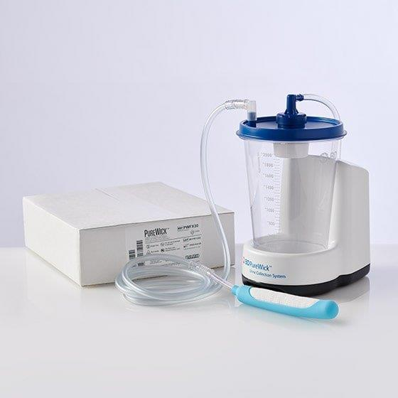


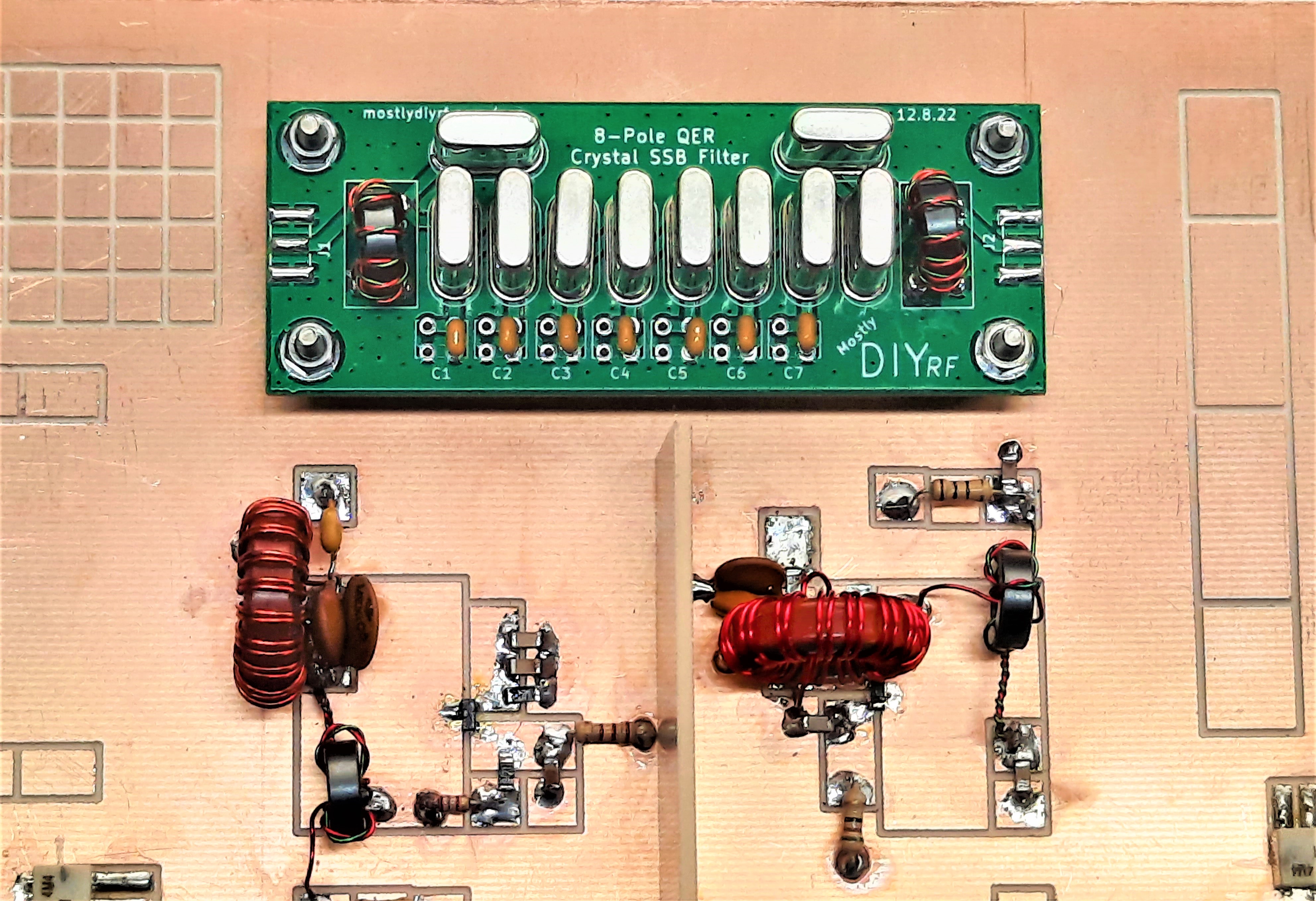


.jpg)


.jpg)


.jpg)


.jpg)


.jpg)