Keeping Things Simple. Update 11-01-2023. Back to the 6BA6 Radio
How About Building Something (HABS)?
Update 11-01-2023. The 6BA6 Parts Arrived
Some of the parts included a panel meter that ranged from 0 to 30 ma and 2.5 Mhy RF Chokes. Back in the day you could fund these items in any decent electronics store but no more.
The meter was selected because the idle current on the 6BA6 will be about 3ma and at two watts the current should peak to 18ma. (about 2/3 scale).


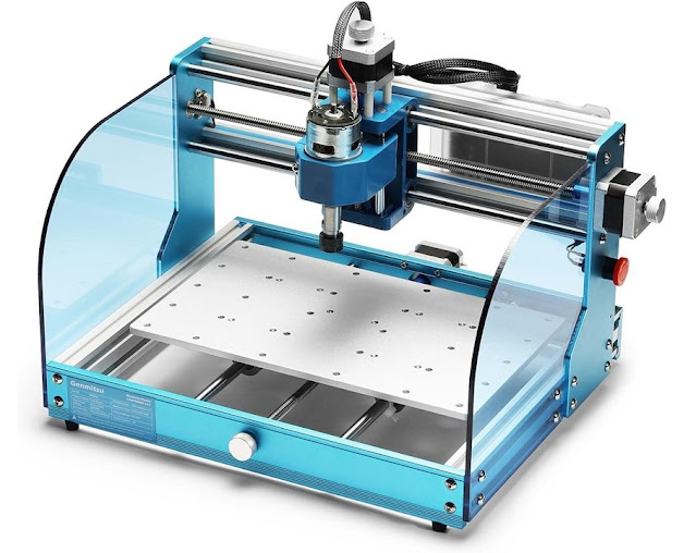
The panel cutout will present some challlenges but with the CNC short work.
Pete N6QW
Update 10-23-2023. It is indeed shirt pocket size.
About two watts out and 60 kHz coverage on 20M.

My daughter took this photo and she asked who else has built a rig this size (mine is 16 cubic inches). I know of three including ZL2BMI and VK3HN and I think a DL station. Likely there are more but if you know of others please email me at my QRZ email address.
Of note this was built in 2011 so soon to be a teenager.
73's
Pete N6QW
Update 10-22-2023. Some Clean up!
I installed a 1pF NPO SMD cap in place of the Gimmick that was installed as the section coupling cap for the Shirt Pocket SSB Transceiver. It is a 603 and not easy to fit to a board. I need to touch up the connections with solder wick

The solder arrived today and so Sunday (10/22) I will do the clean up on the SDR BPF.
73's
Pete N6QW
Update 10-19-2023. A Problem with the Two Band Pass Filter was like finding a Needle in the Haystack.
Initially I built the 40M BPF and proceeded to haywire that into the circuit just to test it and then built the 20M BPF. The final piece was to install the relay switching.
I found once I connected everything up, that the 40M BPF did not work. The 1st thing I thought was a cold solder joint or perhaps when I connected the wiring to the relay, we had a solder blob short. I retouched all of the connections. Still no output (or input) on 40M. So, then I took my ohm meter and switched the relay on off to see if there was a connection to the 40M BPF on both ends. The right-hand side showed a connection, but the left-hand side did not. It showed that it was connected to the 20M BPF.
THIS should have been a huge clue, but I missed it. My 1st thoughts were a bad relay. So, I replaced the relay! The same problem persisted.
I then checked the data sheet for this series of relays (or something close --it was not close enough).

A small note finally became a huge Billboard! It said the coil had no polarity. But what if the specific unit I had did have a polarity.

The two relays were originally installed so that the upper relay pads were connected underneath the board. If the coil had no polarity then this would be OK, but if polarized, the actual terminals were not the same (upper pad connection of one is not the upper pad connection of the other).
Again, if there was a polarity then one relay would not switch and for one band this would be OK. A bit of wiring change so that the upper pad of one relay was connected to the lower pad of the other. That did it! I had a polarized relay! That was the needle.
I made the change on the left relay since the right-side relay was working properly. We now have two bands. I am using the same layout and pads for the Low Pas Filter so I now know what to do.
When it rains it pours. I ran out of solder so had to use some RoHs crap and it makes a mess. I want to go back and clean up the PC Board and re-solder some connections.
The parallel -- you forgot to feed Mary Jo the Big Boy Hamburger before moving to the back seat of the 57 VW Beetle! So always check to see if your relays have polarized contacts for the field coil.
73's
Pete N6QW
Update 10-17-2023. Two Bands on the Homebrew SDR.
When I initially built the Homebrew SDR it was only on one band (20M). I have always wanted to have at least two bands with 40M being the second band. Then the CNC Computer shot craps and while awaiting some parts for the 6BA6 transceiver that are currently on the slow boat from China, I have been doing some one and done projects with the rebuilt CNC.
The addition of a two band BPF Board with an eye to using that same board layout for the LPF is in the one and done paradigm. This video shows how the 40M Band BPF was the 1st to be built and tested. It works!
This is huge and today I will wire up the switching relays and build the 20M BPF. Powering on or off of the two relays switches the networks depending on whether you are operating 40M or 20M.
Nice to be able to fit these small projects into my demanding schedule.
73's
Pete N6QW
Update 10-13-2023. New BPF Installed.
Thank God, the CNC is back working. I built and installed a new BPF today.

The new BPF is on the left and replaces the two IF Transformers. It has a better pass band but did not improve the Pout. We are getting about a watt and can drive the outboard RF amp to about 40 watts.
73's
Pete N6QW
Update 10-12-2023. Now about 800 Milliwatts output from the Shirt Pocket SSB Transceiver.
I made a couple of changes to the Shirt Pocket RF Final Amp stage. For those who actually use EMRFD (mine is a great door stop) the 2N3904 / 2N3866 is straight out of that book. I boosted the output by bypassing the emitter resistors. There was already a bypass installed at the 2N3904 Emitter and adding one on the 2N3866 caused a 4X increase in output. We now see 800 Milliwatts at the output. This needs more tweaking, but we are on the road to improvement.

The power output issue might also be related to the Band Pass Filter. In the upper left-hand corner of the photo can be seen two IF Transformer Cans which are the 42IF123 10.7 MHz IF Transformers that have been modified to shift the frequency to 14 Megahertz.
The interstage coupling cap may be too small which would give a very narrow peaked response. I say this as it seems there is a very small increase in background noise as you tune the slugs, almost like they are not resonant at 20M. One seems to peak but the other one doesn't. More opportunities for imperfections. This might need a change to a discrete component type of filter. Perhaps SMD in the mix!


Observe the transistor with the heatsink located about in the center of the photo. Just to the right of the device is the 10nF and the two resistors whose equivalent value is about 4 Ohms. To the left of that transistor is the 2N3904 and the combo 10nF and the 22 Ohm Emitter resistor.
The IRF510 has a TO-220 heat sink which is not sufficient. Thus, on the underside of the chassis is a slab of copper about 1 square inch, used as additional heat sink material. Heat is always an issue with a compact build. I took a copper plumbing nipple and smashed it flat and drilled a mounting hole through the flattened piece.
Of note look at the output of the IRF510 as that is not the usual install of the Bifilar Wound Matching Transformer. Simulate either configuration, the output is the same. Prove it to yourself. It is a 4:1 match.
73's
Pete N6QW
Update 10-11-2023. Shirt Pocket SSB Transceiver (all 16 Cubic Inches of it) works DX!

Couldn't resist --so hooking up some outboard amps to yield 100 Watts to the Delta Loop, I worked CE7VP thus see the above chart.
The change to the Rx by adding the RF Amp stage made a huge difference on Receive. But the Transmit part is anemic putting out only 200 milliwatts. The outboard linear gets that to about 8 watts and the SB200 about 100 watts. But I was 5X9.

The BFR96 has the same model parameters as the BFR106 and the reference to L1 and L2 was a note from a previous simulation and not germane to this circuit.
I must dig into the low transmit output. The Driver stage alone should be good for 350 --400 milliwatts (straight from EMRFD). I should be seeing 2 to 3 watts from the IRF510.

73's
Pete N6QW
Update 10-10-2023. Thank You Ronald Reagan!
My Rx RF Amplifier works like a charm!

Rx RF Amp installed in the Shirt Pocket SSB Transceiver
73's
Pete N6QW
Update 10-09-2023. Fixing Something 1st.
The whole sojourn with rebuilding the CNC started with the Shirt Pocket SSB Transceiver V.2. When I built the 2nd version (mostly through hole) I ran out of space -- that was almost 12 years ago. Now with SMD this was a chance to sandwich in a Rx RF Amp stage which was not included in V.2. Its absence was evident!


Cutting the Rx RF Amp Board.
It is so great to have the CNC back online.
73's
Pete N6QW
I tested the amp and it works and the next step is an installation in V.2. The CNC is significant in being able to do this.
Update 10-06-2023. 6BA6 Linear RF Amp Stage

Cutting The 6BA6 RF Amp Board
73's
Pete N6QW
Update 10-05-2023. Desk Engrave & 6BA6 Final Amp Board.


The 6BA6 tubes (Driver and Final) will nest between the two 6X2 Island Squares and will be mounted on short pillars. The pads provide connections points for power, signals and components. I have a movie which I will load later today. The Z Axis travel has been minimized.
Desk Engrave
I have an engraving program called Desk Engrave and now I can make nameplates for my rigs.
Part of the N (left side) is missing as I accidently hit the pause button and when I restarted the machine --it missed some steps. You have a choice of Fonts and Size and whether BOLD. The Print Style is Comic Sands.


I had to diddle with the Z axis parameters. Those 4 simple letters/figures have 1000 steps in the program.
73's
Pete N6QW
Update 10-04-2023. Improving Z Axis Travel Time.
The G-Code (machine instructions) is a text file that is automatically generated once you go from the design to the G-code. It was noted as the Spindle is lifted off the cutting plane to move to the next location that there was significant upward/downward travel which adds to the cutting time and adds wear and tear on the Z Axis hardware. I postulated how to fix that problem and my fix worked.
This is likely in the category of those who really know how to use CNC machines will say everyone knows that trick but I didn't, but I do now!
I hope to cut a board for the 6BA6 project yet today!
73's
Pete N6QW
Update 10-03-2023. 1st Board off the Refurbished CNC Mill. Soon Back to the 6BA6 Project.
In my last update and video, I found that the X Axis didn't work and suspected a bad motor. JIC (Just In Case) I found an exact replacement motor and felt it was good business to have at least one spare.
My #3 son suggested swapping cables to the Y Axis and see if it would run the X Axis. That worked! It was not a bad motor nor controller board!
Then I pulled the cable from the Toshiba Controller and with my DSO looked for a pulse on Pins 3, 5 and 7. No pulse on Pin 3. That is when I remembered I had a spare Printer Cable and ran the tests again. We now had a pulse on Pin 3. Thus, the culprit was a bad cable. The spare cable I had was only 4 feet long and we need a 6-foot cable. Amazon is your friend and so one is on the way.
When You Know Stuff, You Can Do Stuff!
Hopefully soon we will be back on cutting some 6BA6 circuit boards.
In a postscript sort of way, my #3 son stated based on the rebuild I did that he would probably hire me should I apply for a job.
73's
Pete N6QW
Update 10-02-2023. Huge Progress!
The Internet strikes again! I found many tutorials on how to set up the Mach 3 CNC software and essentially the info was all wrong.
Not until I checked the Toshiba TB6560 Controller setup did I find the correct Pin Assignments.

Using this as a guide I was able to provide the proper inputs to the Mach 3 software. The video above shows the progress that was made.
I still have an issue with the X axis and the Emergency Stop but we have moved the needle.
This was a giant step forward. Hopefully we will soon be cutting metal and in the event either the X axis on the Toshiba Controller is bad or a bad X axis Motor, two replacements are in the mail.
Can't wait until I can use the machine again. But I have learned a lot about the hardware and software side of my CNC.
73's
Pete N6QW
sUpdate 10-1-2023. Biostar Motherboard. Deep State Secrets.
The Culprit!
.jpg)
When I rebuilt my CNC Computer to load Windows XP Pro, I bought from eBay a Motherboard with a 3 GHz CPU and 8GB of RAM for $28. It all works.
Well almost as the Mach3 CNC software uses the parallel port as an input and output device. Try as I might I could not get the parallel port to function. Using the Device Manager there was no path to installing the LPT1 port.
The Mach3 has a built-in diagnostic tool to check the Driver (to theLPT1) and the test showed the driver was working in the excellent range. It was like failing to get Mary Jo a Big Boy Burger before trying to entice her into the back seat of the 57 VW Beetle.
Then I remembered when I used to be a systems Builder, that often the Motherboards came with a driver disk to load accessories. A check on the web sure enough turned up the drivers and I was able to add some additional capabilities that showed up in the device manager as not being installed. So that was positive. But no LPT1.
I open up the BIOS utility to check the features just installed and in a somewhat arcane menu title I found, an item marked LPT1, and its status was Disabled. Enabling this in BIOS gave you a choice of three port addresses and one of those was the address needed for the CNC.
So a small test shows I now can make some of the axis selections move, but not correctly. An "up" Z axis command moves the table in the Y direction. and a move in the X direction causes the spindle to move down in the Z direction. Now the Pins and Ports configuration selection menu (on the Mach 3 Dashboard) is based on the CNC controller connected to the machine. The right selection of pins and ports makes the CNC cut stuff!
There was an emergency stop installed on the machine and as I found out was in operative. Previously 1/2 the switch was NO and the other half NC. So, to get the machine to work required engaging the switch such as needed in an emergency stop being activated. On was now Off. Switching the wires to the other half of the switch now makes it work so engaging the switch stops the machine as you would expect.
I touched none of the machine wiring so don't know how things could change just with a motherboard swap.
73's
Pete N6QW
Update 9-28-2023. Tales of Woe.
Now I know why the term Plug and Play is really Plug and Pray.
Short story, I had to rebuild the CNC computer, purchase Windows XP Pro Software and a new piece of Mach 3 CNC Software. I also had to acquire a few boards/parts (video card, Parallel Port Card, SATA cables and a SATA Y power Adapter). Along the way the 500GB HDD just purchased from Amazon was bad and had to be returned. So, all did not go smooth!
In the end I do have a better computer and so that is a plus. The old processor was a LG755 and the new is an I3 with 8 GB of RAM.
This morning I loaded the Mach 3 CNC software which in itself is/maybe a problem. I bought the software on eBay for $40 supposedly new. Instead of getting a package I got a link to a download. Normally Mach3 costs about $170. eBay alerts me this morning that the seller has been suspended and I may not get my purchase in a box. Well, I did get the download and it installed FB -- but have not launched it. eBay will refund the purchase price so not a total loss except for time and having to spend more$$$ to get the Mach 3.

The reason for using Windows XP Pro is that the Mach3 software likes and depends on this OS. I got that to load OK.
BUT while the WiFi dongle was shown as connected to the Wireless Router -- Internet Explorer would not launch so I couldn't use the Internet.
Windows XP Pro is not supported by Microsoft nor a lot of the browsers like Firefox and Chrome. That said I did find a browser called "MyPal" and that works. There may be some issues with programs like Netflix but for eBay and downloading software it works nicely.
I had the same issue with another computer where I loaded Windows 7 and MyPal fixed that issue. I suspect Microshaft is in the background with these non-supported systems. Can't connect to the Internet and so not useful and that forces you to buy Windows 11 and soon Windows 12!
We are getting closer, as #3 son is wading through the configuration settings so assuming the Mach 3, I loaded works we may have a machine back in operation. BTW -- most of the time to load any software you have to run the program as the Administrator.
I could not load any Com Ports, so I used a piece of software to add some Com Ports. There is not a "Add Legacy Hardware" menu on my Device Manager -- another challenge.
This is fun! Like a Root Canal without any anesthetic!
73's
Pete N6QW
Update 9-25-2023. CNC Computer Still InOp.
I was able to load the CNC software on to an Old Windows 7 machine and it will function on the computer, but the CNC Mill still sits there without responding to commands. It has to do I think with the Ports and Pins Configuration Menu.
I am in consultation with an expert (#3 Son) so am kind of stuck. He has the Mach III software on his machine and will take photos of his configuration which may give some clues and what I have missed.
Recently I dumped the TV portion of my cable package and switched to YouTube TV (net savings of $100 a month). This freed up a 22-inch non-smart TV which has HDMI ports. My homebrew SDR with the Windows 10 Pro OS and Nvidia Video Gaming Card now has a quite spectacular monitor. A world of difference from the old 17-inch VGA unit.
I have been making many FT-8 and SSB contacts with this homebrew rig and the stations at the other end simply do not know that my rig is NOT an ICOM IC7300. The PowerSDR (SV1EIA Distribution) has powerful features like tailoring the Received and Transmitted audio with a 10 Band Equalizer. The Noise Reduction takes the noise right out of the picture. Frequency stability is with a Si 570 at the helm.


A Chance to Tinker
I strongly suggest you visit N2CQR's YouTube Channel and view SolderSmoke #247 where we discuss SDR radios and the ICOM IC7300. Bill advocates hating the ICOM IC7300 because you can't tinker with the innards.
My homebrew SDR is fully tinkerable and I found I had NIB BPF's and LPF's for 20 and 40M from QRP Labs (Hans Summers). That will be the next mod to add the capability for two bands.
True I cannot dig into the software under a shade tree in the back yard, but with the functionality built in by SV1EIA I do not see that as an impediment.
With winter approaching, I need to get the CNC up and running as I want to get back to the 6BA6 radio.
73's
Pete N6QW
Update 9-23-2023. On the Path to a Fix.
So, it does pour! The video card arrived and I did not realize the install bracket was only 1/2 height. So, I have a fix using a blank filler and overlaying the 1/2- height on to a blank filler plate I can mill out the cutouts using my manual mill. Easy to do. The video card did fix the video issue, but the HDD won't boot.


So, then a bit of brilliance. The PATA to SATA converter board arrived so the solution came to me. Even though the HDD may not boot, I might be able to access the file systems. Thusly I proceeded to install the HDD in my Windows 10 Pro SDR machine as a plain old secondary drive. That worked!

Next, I set up a blank DVD disc as a "USB Stick" and copied files from the secondary drive to the "USB Stick DVD". I found my CNC dxf Files and better yet in the Download File Folder I found application programs for the CNC machine itself. That worked. Most of the critical stuff was in the Documents and Download Folders.
Next, I took the DVD to an old Windows 7 machine and successfully installed many of the application programs. That worked.
I bought a refurbished Motherboard along with a Intel I3 processor and 8GB of RAM for under $50. That is coming. I already had a 500GB HDD and so am enroute to a completely new CNC machine.
The Big Takeaway is the saving of the CNC Files and the Applications programs. The CNC files were literally 15 years of work.
Like many things in our hobby. Many simple tasks take a week or two to implement. Just like Mary Jo, there was significant time that passed before she was in the back seat of the 57 VW Beetle.
73's
Pete N6QW
Update 9-21-2023. She is Broken!
When it rains it pours! My CNC computer is broken and that is what has held me back on the 6BA6 project. Without the computer it is hard to cut PC Board or any metal stuff.

I built this machine about 14 years ago and it now has a problem. As best as I can tell it is that the on-board video card has an issue. In the mail is a replacement external video card. The symptom was color streaking and then fuzzy lines.
This is where a reasoned troubleshooting approach makes sense. I pulled the HDD connection and on post you get the same condition. So, the good news is that the HDD may be OK. The HDD is an old PATA type thus has the big clunky connector on the back apron.
Also coming today is a PATA to SATA adapter connector. It was cheap (under $10) and another test is to install the CNC HDD in another computer as a second drive if only to see if I can get some critical design files off this HDD. Most newer motherboards only have the SATA connector.
My cutting software is MACH III which was loaded on this machine by #3 son. So, if all goes to hell I may have to ultimately purchase that software if I can't access the HDD. KCam which I also use to convert the dxf Files to G Code is on there too, but no longer available.
But if I convert all of my new stuff to Carbide Create it does the G Code conversion. My design system is G Simple (also on this drive) and I find G Simple easier to create my designs than Carbide Create.
Bottom line it has become a cascading problem and not just a simple video card, assuming the external card does not fix the problem.
I was amazed to find out that there are some bargains on replacement motherboards and that may be a follow-on fix is just to bite the bullet and start fresh.
A world of woes. Stay tuned for more exciting misadventures. This is definitely not as much fun as Mary Jo in the back seat of the 57 VW Beetle.
73's
Pete N6QW
Update 9-17-2023. 6BA6 Power Amp
I am modifying this blog using my new laptop which has no Microshaft Office but I did find out that the photo editor lets you draw lines.

Using the components from the SBE-33 tank circuit the wiring would look like this.
- Starting at the upper left is the coupling cap to the 6BA6 Plate. Two important issues are its value and voltage rating. Nominally you will find its value is 1000pF and the voltage rating is like 1 KV or more.
- The variable capacitor on the left will likely only be 1/3 meshed on 20M, so something perhaps around 30pF. The padder capacitor on the right is likely around 300 to 400pF.
- For the inductor I will use an alligator clip to find the right inductance value and then make a permanent connection.
- In some value engineered (the cheap stuff) commercial rigs, the padder capacitor (right) was eliminated and a fixed value cap was switched into the circuit for each band. A lab rat on the production line tested for a nominal value to load into 50 Ohms and the rest was history. This approach did not give much control over loading to vary the power output.
- At the intersection of the coil and the padder cap is the output to the TR relay connection point.
- One really best practice is to connect a 2.5 millihenry choke to the tank output connection and to ground. WHY you ask? Well in the event the Coupling Capacitor connected to the Plate shorts (fails) you have high voltage suddenly connected to your antenna. The 2.5 mHy choke in effect shorts the DC to ground. At RF the impedance of the choke is 2*Pi*F*L which is quite high in comparison to 50 Ohms. At 14.2MHz that is about 0.22Megohms (220K).
73's
Pete N6QW
- Update 9-16-2023. Linear RF Power Output Stage.
We have 250 VDC on the Plate and 150 Volts on the Screen. Our Plate Current quiescent set point (with -3 VDC of Bias) is 8 milliamps. So how does that translate to an output with perhaps 9 Volts PTP of signal input to the Grid, (9 Volts PTP translates to 200 milliwatts of input with a 50 Ohm load). If we had 10dB of gain in the 6BA6 stage that would be 2 watts output.
But calculating RF output is more complex than what I have shown. So, to short circuit the math and mental gymnastics I propose to build a test circuit and run with what I know. Maybe this is like Barbieheimer -- they just hit the ON button. I have started the removal of the tank circuit from the SBE-33 hulk so it shouldn't take too long to whip up the hardware.

SBE-33 Pi Network
73's
Pete N6QW
Update 9-14-2023. So that we cover many interests -- a move from HDR to SDR. Easy to do!
I am in awe at what can be done with a software defined radio, and this goes back to 2011 when I played around with my 1st Softrock transceiver. There was not much hardware involved, and the real power was what could be done with the software. One of the initial pieces of SDR software was the open source PowerSDR which was modified by SV1EIA so it would "play" with homebrew type SDR transceivers. Power SDR was of course developed by FLEX Radio to run the SDR-1000.
Many of the initial rig offerings used the Tayloe Detector for both transmit and receive. When I built my homebrew SDR I bypassed that device in favor of the use of two ADE-1's (DBM) and the obvious reason was that the ADE-1 is inherently bi-directional. So, signals easily pass through the two DBM's with the ease of a hot knife through butter.
I do have some commercial SDR radios including the Hermes Lite 2.0 and the Multus Proficio. But these both are far more complex in the hardware than what I brewed up.
In more recent times I shifted my homebrew stuff to the Raspberry Pi and QUISK. But Power SDR has more signal processing features. Typically, though you need a "Big Box" for Power SD. The Big Box is what lead me to today's posting.
I have a homebrew computer that had Linux Mint20 installed on it, and I also tripped over a box of sound cards from my 1st foray into SDR. So, for a small sum of $30 I bought a Windows 10 Pro, 64 Bit CD and we now have PowerSDR installed (based on the work of SV1EIA) on this machine. For a rig I am using my homebrew SDR transceiver. The all-critical Sound Card is a professional grade M-Audio Delta 44.
The AGC is at 110% (open) so some pumping of the signals. That has since been cranked back to about 85%. I have one of the afterburners in line for 100 watts to the antenna. The 2nd after cooker (a modified SB200) can do 600 watts to the antenna.
In SS#247, friend N2CQR was lamenting that the SDR radios cannot be taken under a shade tree and tinkered with like a 65 Mustang. That said my homebrew SDR can be tinkered with, and you don't need a tree. One mod is to add a 2nd band. This rig is 20M only. possible 2nd bands would be 40M or maybe 15M. My rig needs a simple and durable "plug-in BPF" mod. The LPF is on a Circuit board dongle with the TR relay.
It was all of about 6 hours work to install the software and get all of the setting rights. Easy to do. The toughest nut was to find the drivers for the M-Audio Delta 44 Sound Card (now out of production).
Interesting enough with the new Windows 10 capability several other software packages can be installed so that I can run rigs like the Hermes Lite 2.0 or the Multus Proficio all with this one computer. I even have a Network Switch so that this new computer can be readily switched to the various rigs. Look Ma No Hands!
See the above link for more info on my SDR transceiver.
73's
Pete N6QW
Update 9-13-2023. A Plan.
In looking at yesterday's posting it was sobering to think what I may have at hand is a 29A and we were initially thinking more along the lines of a 44DD.
But my next step is to prototype a 6BA6 Final RF Power Amp stage and take some data. The Audio Amp stage I built is good for more than several hundred milliwatts and so we should try a bit of testing to see what a real-world test produces. A half watt would be enough to drive a small outboard linear amp stage to maybe 15 watts or so.
I have a final tank circuit from a donor part SBE-33 SSB Transceiver and that will give me a starting place. A small breadboard would serve as a chassis and the RF Driving Source would be my signal generator. We would be evaluating the circuit as a RF Amplifier, finding the right tank circuit constants and seeing if the tank could stretch to 15M. We would start with 250 volts on the Plate, 150 Volts on the Screen and a - 3DVC for the Bias to the Grid. The Cathode would be at Ground (or a very small resistance to measure Cathode current).

A TKT -- a good source for small pieces of hobby plywood "breadboards" is JOANN Fabrics and Crafts.
Plywood A bit thin but only $6
Stay Tuned.
73's
Pete N6QW
Update 9-12-2023. RF Power Amplifier Stage.
The garage was again in the 90's yesterday afternoon in between my shifts at the Board and Care Facility so no hardware building. But that did give me some time to "noodle" over the 6BA6 as a RF Power Amplifier.
One of the attributes of the venerable 6BA6 is its abilities / capabilities to be an RF amplifier. But that is really limited to small signals. Think of a 2N3904 which is another excellent RF amplifier. Aside from the ham in JA land who paralleled about 10 of these jewels to get a couple of watts of RF on 20M-- it can't produce several watts with a single 2N3904. A 2N3904 is not an RD06HHF1. A 6BA6 is not a 6146.
So how do we go about looking at the 6BA6 as a RF Power Amplifier and not just as a RF Amplifier. We need to look at the published characteristic curves of the 6BA6. These sets of curves document things like Plate Current versus Plate, Screen and Grid Bias voltages over a range of values. Using things like Load Lines it is possible to impress a signal on the graphs and see the resultant. (The same applies for transistors.)

The other piece is to look at a Pi Network following the 6BA6 so we can determine the values of capacitance the inductor values. The old tune, load and dip AKA TFMS. (Tune For Maximum Smoke).
I found a most detailed reference on the internet that published extensive data on the 6BA6 which lets you tour the tube data.
The snippet of characteristic curves above is telling as the 1st thing that pops out at you is that the 6BA6 is not even as good as the 2N3904 as a RF Power Amplifier!
Look at the intersection of 8 milliamps of plate current and the plate voltage of 250 volts. That might be a 1st cut at an operating point. With that operating point the low plate current signals not much output. That also says the power delivered to the load will likely be milliwatts and not watts. The pate current swing might be as high as 12ma and as low as 4ma for an 8ma swing.
With some of the data so far, we can develop a plate load analysis and have some source data for the Pi Network calculations. A 100ma swing would be nice!
I will try to fill in the data gaps but as a 1st look -- the 6BA6 will amplify but to use my frequent analogy it is a 29A and what we want is a 44DD*. The linked reference from Brimar says it all -- the 6BA6 is a receiving valve! But always focus on the goal and that was to use a 6BA6 in every socket and with that goal are some limitations.
73's
Pete N6QW
* Think Twiggy versus Mary Jo!
Caveat Emptor with eBay and ham rigs advertised as not working and tech specials. I always wanted to own an Austin Healey Bug Eyed Sprite. I think they used tractor motors for an engine. This is a $2K Plus Tech Special. The tires look OK.

Update 9-11-2023. Never Forget!
September 11, 2001, a day of infamy much like December 07, 1941. Some 22 years later, many serving in our armed forces today were not even born yet they are defending our country against any future such events. Never forget!
We also must think about US born domestic terrorists who today look to destroy our country. Pearl Harbor and 9/11 were the results of foreign enemies. January 6th, 2021was purely homegrown and the principal perpetrator has yet to meet lady justice. The wheels of justice grind slowly but are sure and now picking up speed.
Pete N6QW

WE
Update 9-09-2023. Tribal Knowledge Tip. TKT

Above is the most current photo of the reworked 17M QRP transceiver. About a week ago and after some six hours of labor much has changed with the front panel and with the features.
Where the colorful Color TFT sits was the main tuning knob for the VXO. Where the smaller knob sits now (Volume control) was the switch for changing the ranges of the VXO and where the microphone jack and audio jack now sits were reversed. The toggle switch under the Color TFT now switches the LO's on the Si5351.
Just for comparison this is a photo before I switched the microphone and audio output jacks and before the toggle switch was added below the Color TFT.

It is pretty clear that the spacing between the now tuning knob (which originally was the hole for the audio gain pot) and the microphone plug --it is too close and an interference problem. Thus, the swap.
But that raises an ugly problem with the panel. The hole for the audio jack is for a 3.5 mm standard audio jack and the hole for the 1/4-inch microphone jack is almost 3/8 inch in diameter.
The former audio jack hole can be enlarged (and it was) to accommodate the 1/4-inch microphone jack. But the former microphone jack hole is way too big for the 3.5mm audio jack.
Our Tribal Knowledge Tip shows how to fit the 3.5mm into the 1/4-inch jack hole, and it involves digging into the hardware junk box. Of note many small toggle switches and other panel controls frequently come with a lot of extra lock washers, and flat washers. When I smoke a small pot I keep the nuts, washers etc. and just excess the rest. Often, I will pull the bad innards from the metal housing as the metal housing is now a panel bushing for passing wires through a chassis panel. So, I have a big hardware junk box.
My 3.5mm to 1/4-inch adapter involves three washers with the center washer being a lock washer type. It is helpful to have a set of jeweler's files to enlarge some of the holes. I have found that many of the small hardware lock washers are actually 3/8-inch OD -- a huge benefit!
Starting with the washer in the upper left-hand corner this goes on the back side of the panel. The lock washer fills the space in the hole itself and the bottom right-hand washer goes on the front panel. Think of it like a sandwich.

Even this new arrangement is tight (Mary Jo) but is a lot better than the original.
Stay tuned.
73's
Pete N6QW
BTW: Bad News for some officials who served POTUS 45. Fulton County Jail likely will need some more space. Maybe some will learn to cook like in the scenes from Goodfellas! Remember slice the garlic razor thin for best flavor.
Update 9-08-2023. A Question about the 33pF Cap on Transmit. See yesterday's posting.
Yeah! Someone is reading the Blog and overnight I got a question. The question asks when you shunt the 33pF to ground on transmit aren't you shunting the transmitted signal to ground. The simple answer is Yes BUT what you are actually doing is paralleling the 33pF with the 150pF which is the 1st cap in the network. (With thanks to Craig for the question.)
This is why you need to use LT Spice. I simulated the Low Pass Filter in LT Spice which is shown below. The 12 Turns and 13 Turns were converted to their inductance values. Essentially on Receive the 33pF is not grounded or appearing as a shunt across C1 (150PF).
But on transmit the 33pF is grounded through the 1N4007 and in effect is paralleled with C1 making that combination 183pF.
Here is the LT Spice with C1 = 150pF (Receive).
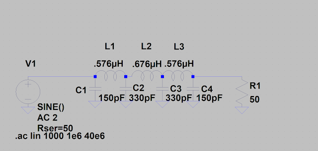

Now the network with the 33pF shunted to ground which now makes C1 = 183pF on Transmit.


The addition of the 33pF has little effect on the shape of the LPF curve in the transmit mode.
A really excellent question and some 16 years later I am glad that the answer can be shown with LT Spice. NOW I must be critical about my design! I should have used the T-37-6 cores versus the T-37-2 as the T-37-2 cores are on the ragged edge at 18 MHz.
The LT Spice simulation does not discriminate about which cores -- so the inductance values are correct, but the core choice may actually be attenuating the signal. If you build this LPF then you should use the T-37-6 cores and use the inductance values but adjust the turns. The Al value for the T-37-2 = 40 and the Al Value for the T-37-6 = 30. This would make L1 about 14 Turns (13.8) with the T-37-6. Likely my choice of the T-37-2 was a case of IUWIH. I Used What I Had in the junk box.
The next step is to make the T-37-6 cores (L1, L3) 14 Turns and L2 = 15 Turns and this is where your beloved Nano VNA can be used. Terminate the network with 50 Ohms and look at your pattern. When you wind the cores make sure the turns are evenly spaced and "tight" -- tight is right no matter whether winding toroid cores or Mary Jo in the back seat of the 57 VW Beetle!
Now this diode steering of capacitors to ground is a subject of a patent issued to Mr. Jones at Ten Tec for the Jones Variable Crystal Filter. Ten Tec used varactor diodes that had a variable voltage applied to the varactor diode, so its capacitance change affected the shape of the filter bandpass. One Filter could be "tuned" with a voltage so that with one setting it was a SSB filter and with another it was a CW Filter. Tribal knowledge here on Crystal Filters -- Less Capacitance = SSB and More Capacitance = CW.
BTW in the event when you did the simulation you made the value 33mF versus 33pF. Then indeed you would be shunting the transmitted signal to ground.

More fun with the electrons.
73's
Pete N6QW
Update 9-07-2023. An interesting BPF Form.
Let us start at the beginning in 2007, where I began my 1st dabbling at producing a shirt pocket transceiver. I chose 17M as that was a new band and I also chose the 4.9152 MHz home brew filter based on that being the filter in the Elecraft K2 and it would work on 17M.
This has been documented on my JES Systems Website HERE
Recently I repaired the Shirt Pocket SSB transceiver, a follow on to this 17M radio, and in doing so ended up with a spare Si5351/Arduino assembly.
The original frequency scheme for the 17M radio was a Crystal Switched Heterodyne Frequency Doubling LO which used 11.5 MHz computer crystals in a VXO to produce a 23 MHz injection frequency. This covered most of the band, but it missed FT-8 and some area around the18.130 MHz range. K8IQY gave me the idea for the frequency doubling and the bonus -- it really expands the VXO range by 2.
Time to fix the limitations with the VXO with a swap to the Si5351 and Arduino. This was about 4 hours of work spaced over three days (my limited schedule).
In reviewing the project on my website, I discovered a cousin to the Drake TR7 BPF approach. The hand drawn schematic for the final amplifier was based on the work of Zack Lau W1VT in a transceiver (7 MHz CW) that appeared in QRP Power.
Essentially all signals on receive and transmit go through the low pass filter. So, any signals above the operating frequency cutoff are not passed through the receiver. Some clever diode switching/steering puts in line the Receiver RF Amp stage on Receive and from there to the BPF. On transmit two diodes essentially remove, block and protect the Receiver RF stage from the transmit RF signals. Thus, on Tx we have the BPF, the PA Stage and LPF.
For those who have trouble with schematics here is what happens On Receive the output from the LPF passes through the 33pF cap to the base of Q4. The Source voltage to the Rx RF Amp also steers the signal output to the IN4007 on to the BPF. BTW the 1N4007 power rectifier is similar to a PIN Diode so don't use a standard 1N4148 diode.
On Transmit the other end of the 33PF is shunted to ground through another 1N4007 so no RF on the base of Q4. With no voltage applied to Q4 on transmit it is OFF and NO steering voltage is applied the 1N4007 connected to the BPF.
So, this might be the "how" to connect a LPF to a HPF with the PA in the middle on transmit. BTW Q3 was later changed to a MRF262 (no longer available) which produces 3 watts on 17M and no Bias circuit to fool around with. The BPF transmit chain and LPF are all located on a small board bolted to the back apron of the chassis box.
For tune up purposes an old technique of unbalancing the carrier is used. The Balanced Modulator is also the Product Detector and is a diode ring with both carrier and phase balance.


7X7X2 Chassis is the Case.
Now something about the Si5351 and Arduino. My good friend Bill, N2CQR is a fundamentalist with regard to not using Digital Frequency Generation. His thing is LC VFO's and his most recent project, a 10/15 Meter transceiver successfully employs a low frequency VFO (3.5 MHz +/-) with a 25 MHz Crystal Filter so that two bands are easily covered with a single VFO. Bravo Bill!
Look at the Color TFT display face on my rig. A simple toggle switch changes the range of the two VFOs but just as easily one LO range could be 15M and the 2nd scale 10M and a DPDT toggle switch would control shifting the LO as well as control the relay switching of the BPF and LPF networks for the two bands. Easy to do.
BTW the Arduino code has VFO Memory so where you leave one band will come back when you toggle between bands -- not so easy to do with an LC VFO.
I find smaller chunk projects especially where just some mods are done to existing rigs fits with my very limited free time.
73's
Pete N6QW
Update 9-06-2023. Band Pass Filters
In the most current Solder Smoke Podcast SS#248, N2CQR shared the RF evaluation work he was doing with his new toy the 10/15M SSB Transceiver. He looked at various filters in this rig using a Tiny SA. He is soon to have a Tiny SA Ultra purchased at discount from Alibaba Express so we can expect more analysis work from Bill.
I mentioned that in the course of repairing the Drake TR7, I discovered that Drake didn't use Band Pass Filters (per se) but on receive cascaded a Low Pass Filter along with a High Pass Filter to form a Band Pass Filter (on Receive). But for transmit the connection between the filters was opened and the Power Amplifier Brick was connected after the LPF but before the HPF. The two graphics below show that scheme.


I got a note from Todd, K7TFC that he had received an inquiry from a prospective customer for his P3ST kit if the BPF in that design could be placed ahead of the steerable Rx RF Amplifier. The current design (because of the simplicity) was amplifying the whole RF spectrum and great reliance was placed on the simple BPF to screen out only a small portion of the band. Likely very strong out of band signal might show up in the background, although I never saw that. But we do have purists in our ranks.
This caused me to rethink the Drake approach used in the TR7. Suppose you had the combo LPF HPF on Receive what would that look like.
So, taking a stock design for the LPF (as used in the P3ST), I went to the internet and looked for a HPF calculator and set a low frequency cutoff of 13.9 MHz and selected a 7th order for steeper skirts. The diagram following the basic 20M W3NQN LPF is the add from the calculator.


Surprise! The 1st cut of the resultant BPF on receive looks like this. I would like to see a smoother band pass, but this was just the 1st cut.
Of note the 2nd Harmonic is a whopping -120 dB down.

In my gut I thought if I added one resistor in between the section (50 Ohms) we might improve the curve. Look for R2.


It did indeed flatten things, but the center of the band pass is 15 MHz and so we need to shift that downward to 14 MHz. I may have picked a cut off frequency for the HPF at 13.9 MHz as too high. So, we need to run that simulation. But this shows some promise.
Second run with a lower cutoff for the HPF made things worse! I picked 12 MHz!


The third run is at 15MHz for the HPF cutoff!


Boom -- That is getting to more of what we would like to see. The 2nd Harmonic is still -120 dB down.
But our center frequency is still @ 15 MHz and so now we need to look at the cutoff Frequency of the basic W3NQN filter.
This is ugly! But here is a sample of the output between the sections.

Same plot below with a 50 Ohm load between sections

This is a plot of the W3NQN as a standalone terminated in 50 Ohms.

So, we must conclude that the HPF is loading the LPF. But the cutoff of the LPF is too high as it is flat to 17 MHz.
So, more issues to resolve in that the LPF cutoff needs to shift to like 15 MHz and we need to evaluate the loading issue.

Keep your dial set to this frequency.
73's
Pete N6QW
This is a worthwhile filler while I try to get back to building Tube boards.
Update 9-04-2023. Happy Labor Day!
If there is any labor, going on today let us hope it is at the workbench working on some special radio related endeavor.
Bill, N2CQR and I, will be doing a podcast this morning. Actually, Bill does all of the work and I just ride along for the fun. Wished I had more to contribute but my time is very limited.
73's
Pete N6QW
Update 9-03-2023. Exciting News from Mostly DIY RF.com The P3ST SSB Tri-Band Transceiver!


Sign up for the Newsletter from Todd, K7TFC, where today he released an update on his Tri-Band SSB transceiver based on the P3ST design.
Todd announced the release of the rig on the birthday of two famous folks on or about December 18, 2023 (just in time for Christmas). Those two celebrants are radio pioneer E.H. Armstrong (inventor of the regen receiver, the superheterodyne and FM radio) and the former husband of Jennifer Anniston and Angelina Jolie -- Brad Pitt no less. Commentary on Pitt's purported current girlfriend -- about 30 years younger than Pitt -- go Brad!
Look carefully at Todd's offering as it is feature rich with plenty of space to access the boards to address the needs of those of us with FFS (Fat Finger Syndrome). This same open-air space feature facilitates swapping in your own modules, so it is an experimenter's platform.
The other bonus is that you can pull the sub-boards from the mother board to trouble shoot that specific board. Thusly you will only blow up (smoke) one board and not the whole radio.
In addition to the transceiver board Todd is releasing the LO BFO board which is used with the P3ST but also is a standalone for other projects.
Visit his website and get signed up. While you are at it stock up on some of his current boards like the DBM's.
73's
Pete N6QW
Update 9-01-2023. Information Sharing.
I ride along with Bill, N2CQR in his SolderSmoke podcast which can be seen on You Tube. Of note is #247 where we discussed Todd's (K7TFC) Mostly DIY RF Newsletter and a survey he conducted.
One of the survey questions was to address features that customers would like to see. One of those features is a S Meter built into the display. N2CQR stated he had S Meter envy and even though that is something often seen on Color TFT displays, he had some 16X2 LCD's that he thought would be cool.
Well, there are two issues with LCDs, and the 1st is how to display bars and the second is how to make the bars move.
About two years ago I discovered that you can easily create (easily is a relative term) custom characters for the LCD and to call them up at will.

Initially I started with the dash line (one of the standard keys) but when displayed that was like looking at a 29A from afar (not much to see). What you needed is more like a robust 44DD to show on the display.
What you see in the above photo is a custom character that is indeed more in line with our established visual template. Code abounds on the Internet for making custom characters and "easy to do".
The code to make the bar move is more complex. You take an analogRead on one of the pins and massage that reading to display a log function which produces a value (val). Then using the if/else logic you can set parameters for which blocks get displayed. Hey not real scientific but great for wiggling blocks.
BTW this display is for use with a VU2ESE Bitx40 board that was converted to 17 Meters. The B on the 1st line is to show that the 2nd VFO range is being used.
For USB the LO is set at 30 MHz which with the 12 MHz IF yields 17M USB (sideband inversion as the on board LSB BFO is used). The A LO is set at 6 MHz which then gives 17M LSB. This is an easy way to put the Bitx40 on USB while keeping the LSB BFO frequency.
There are two sets of tuned networks on the board that must be moved to 17M. It is not enough just to change to LO range. LT Spice is your friend. QED.
When you know stuff, you can do stuff. The garage is like a bake oven so no build stuff!
For those standing on one leg, holding your pee -- a new podcast is soon to come where Bill is the Concert Master and I contribute as I can.
73's
Pete N6QW
Update 8-31-2023. 6BA6 Amplifier Stage.

First apologies for not showing any more hardware but my typical day has me visiting with the XYL at the Board and Care facility in the morning and later on in the afternoon. The interval time of late has been simply too hot to work in the garage shack. When its 95 degrees in the garage it is like trying to build stuff in a sauna. So, this weather may persist for some time.
That said the above amp stage is a good candidate for the IF amp design and also in general as an amp template for the Receiver RF amp stage and as the Driver stage. In these uses the 68 Ohm would go to ground and the input circuitry would be adjusted. Ditto for the output circuitry.
Switching gears, the Gang is being rounded up and getting called to justice. Rudy is going broke fast and in his latest court ruling will likely see a huge judgement against him. Navarro will have his day in court soon sans his claim of executive privilege. Eastman is on the verge of getting disbarred in California. You can run but soon you get busted! The bigger fish are getting fried!
73's
Pete N6QW
Update 8-29-2023. Back to the 6BA6 Project.
As exciting as it was to fix an old friend, we now head back to our 6BA6 project. But we did get some critical input and that was the viability of making contacts running only 2 watts. So, our goal is to drive for that as an output from the 6BA6.
Below is the output stage of a Swan 120 using a 6DQ5. My SW-120 can produce in excess of 100 watts in tune. Its plate dissipation is only 17 watts. The 6BA6 is over 3 watts. Thus 2 watts output should be possible.

Some things to note in this schematic are that we need to supply some sort of bias to place the tube in a region that operates in a linear fashion (that is why they are called linear amplifiers). Next is the output network which is the classic Pi Network configuration (because it resembles the Greek letter Pi).
Also of import is that the Pi Network provides front end tuning for the Receiver section. C16 the 10PF is the pickoff point for the receiver. My intent is to switch the antenna to a separate Band Pass Filter feeding the input to the 6BA6 RF Amplifier located on the Audio Amplifier Board.
There are also a few trimmer caps needed as a part of the neutralization circuit.
But all important is that while the 6BA6 may be designed to output 2 watts it can only do so if there is sufficient drive. If you don't have an ample gas supply, (via the gas pedal) the Maserati will never hit 120 MPH.
So, let us look at some math. If our output is 2 watts or 2000 milliwatts then with 10dB of gain in the 6BA6 we would need an input 200 milliwatts. But if the output stage is only 50% efficient (typical) then the number is 400 milliwatts of drive. That might be hard to do in a single stage following the transmit mixer.
More likely we would need 13dB of gain from the output stage where the Pin would be 200 milliwatts and at 50% efficiency the output would be 2000 milliwatts.
If we could only muster 100 milliwatts from the driver stage, then our Final Amp (50% efficiency) would have to have 16dB of gain (not likely).
This is where the rubber meets the road. We need 200 milliwatts of Drive and 13dB of Gain from the Final Amplifier stage.
So, what is 200 milliwatts of drive? The math says you take the Peak-to-Peak value and square it and then take it times 2.5 (50 Ohm load). The approximate value is 9 Volts PTP. Squared = 81 and time 2.5 = 202.44 milliwatts.

If we take our 9 Volts PTP and convert to RMS that equals 3.1815 Volts RMS. Now that squared and divided by 50 Ohms = the power in watts and times 1000 = Power in milliwatts. So 3.1815^2/50 = 0.202438845 Watts. Or 202.44 milliwatts. QED!
Make your life easy just take the PTP and square it and then multiply by 2.5 and you have power in milliwatts with a 50-ohm load!
73's
Pete N6QW
Update 8-28-2023. Sometimes you get Amazed!
Yesterday mid-afternoon after fixing the LO & BFO I tuned across the band and there was this very loud SOTA station calling CQ on 20M. Well as it turned out it was a local ham on a small hill in Newbury Park (my QTH). I called him and got a 5X9 wherein I came back with "running a homebrew QRP". He asked about the rig, and I could tell he was blown away -- and also a new ham. He then asked how far away (stations) I worked, and I cited that when 1st on the air it was not unusual to work into the Midwest or DX.
Original V1 with an after burner and VXO
Last night I worked K0HUU in Springfield, MO running only 2 watts which reaffirmed my earlier statement. I am just imagining how many stations I could work running the 100 watts after burner. Life is too short for QRP!
But this is a data point for the tube radio -- if I can coax 2 watts out of a 6BA6 then it would likely do the same as the Shirt Pocket SSB Transceiver.
Note in the upper right-hand corner of the below photo (almost obscured) is the V2 Rig (Juliano Blue).

73's
Pete N6QW
Update 8-27-2023. Fixing an Old Friend.
In 2011 I took on a challenge to build a Shirt Pocket SSB transceiver. I was successful! The 1st version was 3X4X5 and you needed a huge Shirt Pocket! The 2nd version was 2X2X4. Yes, before QRP Quarterly made a left turn (versus a right turn) it was an article in that publication.

The 1st version suffered a catastrophic failure and was cannibalized to keep some of the boards and rebuilt.
Both units had a 4.9152 MHz homebrew crystal filter and used a crystal switched VXO to cover about 60 kHz of 20M. The main difference between the V1 and V2 is that V2 has no Rx RF Amp stage to conserve space.
In 2019 I rebuilt V1 (using the Si5351) but the LO had an issue. With the 20M band beginning to show a marked improvement at night this prompted another rebuild this weekend to add a new LO.
So having just bought a new batch of Arduino Nano's I programmed one to fit in the radio. Running on the USB port of the computer the module worked perfectly.
Long ago after the man himself (Banzi) said use a 7 to 12 VDC, I adopted a standard 9 VDC regulated supply to all my Arduino Projects. I power on the assembly with 12VDC using the 9 Volt regulator -- a white screen and no LO or BFO. Running a small test, I powered the mini-USB with 5 VDC from a supply -- all worked! Back on the 12 VDC (9 VDC Regulated) and nothing. There was 9 VDC to Vin and there was 5 VDC and 3.3 VDC on the Arduino Pins -- it just didn't fire up.
So, then I went to an older Arduino and programmed that unit and connected 9 VDC to Vin -- it worked! Now the difference is that the old boot loader uses the FTDI chips and the new boot loader the CH340. I did load the CH340 code to the new Arduino and I know it works on 5 VDC via USB but not on 9 VDC to Vin.
We have an important piece of info in that with 9 VDC the on-board Arduino voltage regulators produce 5 VDC and 3.3 VDC so the internal voltage routing is present.
I have not looked at the Arduino schematic to see where there may be a break down in voltage routing but certainly a head scratcher. Has anyone else seen this issue? I have two other NIB Arduino's but am loath to do anything with those until a bit more investigation.
Here is V1 with a new Color TFT versus the VXO.


20 Meters was hot last night, and we are getting over a 1.7-watts of RF.
73's
Pete N6QW
Update 8-25-2023. A Twofer!
In an earlier solid-state SSB Transceiver project (P3ST), I attempted to use the same device in most of the sockets -- the device of choice was a 2N2222A. Five of the seven transistors were indeed that same device. Of note the audio preamp and the microphone amplifier used the exact same circuit and so we repeat that experience with the 6BA6.
I found a circuit in an internet search with credit to Fred Nachbaur and the partial schematic is shown below (his project was an AM transmitter with a 6BE6 in the subsequent stage). The 6AU6 and 6BA6 are close cousins and substitutes for each other. Of note the 6BA6 Cathode is actually Pin 7 but since they are externally connected -- they are interchangeable and equivalent. This is a starting point. We might think of R4 as 68 Ohms.

For the 1st audio stage, I would move the potentiometer to the output side as this would control the input to the final 6BA6 audio stage. For the microphone amp I would leave the circuit as is. For the plate supply I would use the +150-volt rail on my power supply adapter board.
The magic number for today is P01135809.
The only circuit to be further defined is the Product Detector which will be a Triode connected 6BA6.

Stay tuned.
73's
Pete N6QW
Update 8-24-2023. The BFO Circuit.

This is a lift from one of the Swan SSB Transceivers and there is some important information in the diagram.
That important info includes no tuned circuits in the two outputs and the two critical Pins are Pins 5 and 6. Thus, when arranging the tube socket the tube orientation should be such that output taken off of Pin 5 should go to the left (Balanced Modulator) and from Pin 6 to the right (Product Detector).
My power supply breakout board has a +150 VDC regulated output and that will be used as the plate supply.
Thus, we will use this schematic for our parts layout in the center section of the circuit board. Next to the graph paper to finalize the parts layout.
When the circuit is built and operational, we will need to look at the output levels as one of circuits is a diode ring. I am contemplating the use of matched Schottky diodes the 1N5711 and figure we need to assure the output is in the 1-to-1.414-volt range (4 to 7 dBm). Its power dissipation is 400 mw and so something in the 4 dBm to 7 dBm would make the most sense.

73's
Pete N6QW

"Rudy, America's Mayor and his Mug Shot"
Has anyone spotted this Mug Shot on a T-Shirt that is for sale online? $25 on eBay

Update 8-22-2023. Board #2, 1st Cut.

Yesterday I waxed at how the 2nd Board might appear and now I sketched something out as a notional 1st look. The BFO feeds both the Diode Ring and the Product Detector and thus its location enables short direct connections.
The Microphone amp is located close to the Diode Ring Balanced Modulator and in turn the 1st Audio stage follows the Product Detector. Several of the 6BA6's will be connected as Triodes as outlined very early in this thread. (Less parts and simpler circuitry.)
The next step is to use our graph paper to spot the individual part locations. A bit tedious but worth the effort.
Hearsay has it that in Beverly Hills there are many liberal groups holding Trump indictment parties on Thursday and are anxiously awaiting the release of the mug shot T Shirts.
Stay tuned.
From a soggy and earthquake shook SoCal.
73's
Pete N6QW
Update 8-21-2023. The Next Board.

Our next board has many functions and not unlike what I did the P3ST Project, once built results in a substantial part of the whole project. This board enables the verification of:
- BFO (9.001500 MHz for USB) - 6BA6
- The Product Detector - 6BA6
- The Microphone Amplifier - 6BA6
- The Balanced Modulator - Diode Ring
- The Audio Pre-amplifier - 6BA6
- Using the IF output from an external radio IF Output stage and the final Audio Amp stage -- we can check how the back end receives.
- If we power on the Microphone Amp and the Diode Balanced Modulator (plus BFO) we should see a DSB signal output.
So indeed, we will have many of the bits and pieces of the project with just this one board. We also need to look at the plate and screen voltages, so we do not smoke any tubes. Since it will contain four tubes the board size looks like it will be larger, we return to out graph paper to plot the layout.
Some things pop out at you as one contemplates the board layout. First is the BFO which is common to the Receive and Transmit functions as it feeds the Balanced Modulator and the Product Detector so maybe a location in the middle of the PC Board.
The 1st Audio Pre-Amp stage follows the Product Detector which signals a close proximity to each other. Likewise, the Microphone Amplifier is ahead of the Balanced Modulator thus again a proximity to each other.
One could make the argument on one side of the board contains the Microphone Amplifier and Balanced Modulator and the other side the Product Detector and 1st Audio stage. The BFO fills in the middle space.
We had an exciting 5.1 magnitude earthquake only 24 miles from our QTH yesterday and that was on top of about 3 inches of rain. Now all we need is fire, famine and pestilence and we have the four horsemen of the Apocalypse. Oh, wait we have the pestilence, a political figure.
73's
Pete N6QW
Update 8-20-2023. Audio Amp Testing.
Basically, the 6BA6 can be used as an audio amp! It is not a 6AQ5, 6EB8 nor a 6V6 but should give enough volume to operate a small speaker.
The operating conditions were 275 volts on the Plate and 185 volts on the Screen. I want to test the tube with 185 volts on the Plate and 150 Volts on the Screen for better tube life. The tube was as hot as firecracker, and we must keep in mind the plate dissipation is slightly more than 3 watts!
The output seemed to increase as you went up in frequency. It should do OK in the 300 to 3 kHz range.
Exciting times. Watch eBay and Amazon to see who the 1st is to have T shirts with the Trump Mug Shot. Likely it will be Trump himself so he can pay himself and his lawyers. As Tom and Ray (the Tappet brothers) would say -- this is shameless commerce.
73's
Pete N6QW
Hurricane Hilary is likely to pass by our QTH this coming weekend. Just In Case (JIC), I dug out an emergency radio which you can see here.
Update 8-18-2023. Wiring.
My other life keeps affecting my hobby life but today got some wiring done. Power up and test tomorrow.
[This was an invaluable exercise as I could see that I should have removed a bit more material on the underside as the pass through got close on connections to Pin #1. That is the advantage of a prototype.]


The 4-lug terminal strip will have +185, +260, Ground and 12 VDC. The audio output connects to a two-lug terminal strip on the top chassis.
TIT!
73's
Pete N6QW
Update 8-15-2023. Parts Fit Check.
Sorry about the two-day hiatus but my day job took over the schedule. I did a parts fit check for the audio amp stage. Looks OK.


On the underside will be a terminal strip for bringing in the power wiring and a few more parts. I will now remove the copper from around the holes that are not ground and solder up the tube pins. Maybe later today.
TIT -- the 4th indictment has hit the streets!
73's
Pete N6QW
Update 8-13-2023. Adding More Components.
I spent yesterday's efforts on installing the major hardware components. This work placed particular attention to the tube socket orientation so as to align with other pieces such as the output audio transformer and input tuned network for the RF Amp stage.
The resistors and capacitors will be installed on the top of the ground plane much as you would do with a printed circuit board. The tube placement factored in the space needed for short direct connections to the tube base. That is the next step, the addition of the caps and resistors and a few terminal strips.
Using the graph paper is a 1st and important critical step.


The fun starts here so stay tuned.
TIT so watch for another indictment next week.
73's
Pete N6QW
Update 8-12-2023. Hardware Operations.


Yesterday I made some cutouts for the tube sockets and one of the tuned networks used in the Receiver RF Amp stage.
The 1st step was to remove the underside copper area from the RF Amp area (second photo shows the removal). The top surface is the ground plane.
Today I hope to add the other components to finalize the layout.
TIT.
Stayed tuned!
73's
Pete N6QW
Update 8-11-2023. The Start Of the 1st Board.

In the photo above I used the CNC Mill to remove the copper on the UNDERSIDE of the prototype board as I was using the double-sided copper board. Otherwise, we would have a potential short problem.

This is a fit check to determine where to place the tube socket location so that the pins and components would clear the copper area. The top surface keep in mind is a continuous copper plane. Note I left copper around the cleared area so that the contact would be made with the aluminum pillars to the bottom plate that will hold all of the assemblies together.

I tested my 7 Pin tube socket CNC Mill cutout program to see if the size was correct for the socket I was using. This is just a piece of scrap PC Board.

It was correct as shown with a socket in the hole.

Shown above is the bottom side with the cutout area for the Audio Amplifier. The hole marks in the corners are the drill spots for the 4-40 bolts that will connect to the pillars.
Today I need to do a similar copper removal on the left side of the board as this is for the Receiver RF Amplifier stage.
The wiring of the audio amp is fairly straight forward as there are only five other components consisting of three caps and two resistors. The resistors and one cap have one end go to ground.
Now a word about a CNC Mill. Today such a tool can be had for about $300 and not $3000. It makes for short work in the build of the 6BA6 SSB Transceiver. See the following link for info about CNC Mills.
FOR THOSE WITHOUT A CNC MILL SIMPLY GET SOME INSULATED PILLARS (NYLON) AND RAISE THE TUBE SOCKET ABOVE THE GROUND PLANE -- FLARE OUT THE PINS AND YOU ARE THERE. DON'T YOU JUST LOVE WHEN A PLAN COMES TOGETHER!
This is me 64 years ago building tube rigs.

The tube assembly just above my hands is a 10M CW transceiver. My main rig was a DX-100B and the SX-99. When I was in Vietnam the 1st time, my dad sold this whole station for $100 to some kid who just got his ticket. He explained to me it was just sitting there and I might not come home. Yes, N2CQR I did have a QF-1 Q Multiplier.
73's
Pete N6QW
Update 8-10-2023. Board Layout.


The last thing I do is to turn on the soldering iron and the 1st is to get a chunk of Quad Pad Paper.
I have decided the module boards will be 3x4.5 inches as the Single sided copper vector board comes in a chunk 4.5 X 17 inches. I would get 5 boards out of one piece.
Starting from the audio amplifier and noting this same board will have the Rx RF amplifier on the board I allocated (eyeballed) a rough estimate of board area. With the schematic as a guide, I made a 1st run at space allocation and this looks feasible.
Aside from the 6BA6 and transformer it looks like we have only 5 other components (resistors and capacitors).
Likely I will include a top mounted shield between the circuits.
The next step is to take a prototype board and cut the holes for the tube socket and the audio transformer. This will not be the final board but will give me a fit check and a finalized layout. I think there will be a bit of tweaking to get this to work. A few hundred milliwatts is all we need for a set of headphones.
In the past I inadvertently ordered a piece of double-sided copper vector board, and this will be used for the prototyping.
Of note I will install the RF Amplifier tube on this board as its filaments will be in series with the Audio Amp stage.
The political drama is certainly heating up and this is a drag on the creative homebrew process.
TIT!
73's
Pete N6QW
Update 8-08-2023. Not My 1st Rodeo.


This a six-tube 20M SSB/CW receiver I would grade as a C in performance. The IF is 9 MHz and the solid-state VFO at 5 MHz which (gulp) drifted.
The Product Detector/BFO was a 12AU7 and the audio was a 6EB8. The IF lineup was a 6CB6 and a 6BA6.
This was built as a companion to a two tube CW transmitter.
Our goal for the 6BA6 project is a B+ or better for the receiver. The performance issue for the above project is that it was too compact, and heat was a problem. On the underside, parts were shoe-horned into the chassis which make servicing difficult. While cute not the best plan for a rig that will be used beyond a casual basis.
Note: None of this information is covered by a DOJ Protective Order and therefore can be freely shared.
TIT!
73's
Pete N6QW
Update 8-07-2023. More Construction Information.
(Note I am awaiting a shipment of single sided copper vector board so actual construction won't take place until that is in hand.)

"I love the smell of Napalm in the morning!"
The thoughts of Robert DuVal's character in the movie Apocalypse Now. I loved that movie and drew a parallel to my CO. Too bad Cadet Bone Spurs or Tommy Tuberville never served!
But that movie was very well crafted and brought back many memories as did Coming Home with Jon Voight. On my return from my 2nd trip to South Vietnam I was on a C-141 Star Lifter and for 13 hours had a chance to stare at 20 aluminum caskets draped with the American flag. We were all coming home but some in a box!
We want our 6BA6 tube rig to be well crafted and here are a few tips.
- Prototype all circuits before you finalize your build. We want this radio to work reliably and not for just 5 minutes.
- Plan the build working from the back end to the front end. As you complete various circuits these become a part of the test system. Build the audio amp 1st and then build the BFO, Product Detector and 1st audio stage. You likely will have to wire in filaments of tubes on the board that are part of the transmit chain like the Microphone Amp. That is just to balance out the filament string at this point.
- Keep data, records and digital photos as these will be invaluable later on.
Note: None of this shared information is covered by a DOJ, Protective Order so we are free to provide this to you.
73's
Pete N6QW
Update 8-06-2023. Construction Tips using the Single Sided Copper Vector Board.
Aside from CNC Milling my PC Boards, the second-best method FOR ME is the use of the Single Sided Copper Vector Board. The following examples show the why.


The above two photos show the W7ZOI HYCAS circuit long with the S Meter/AGC and the Product Detector. The second photo shows how I wrapped around the base PC board pieces of double-sided PC board to form a box.
The icing on the cake is the use of standoff threaded aluminum pillars. These pillars now enable installing a bottom plate or affixing the assembly to the chassis. They also provide a ground path for the circuit board and the inner shielding. See the last photo.
The huge advantage aside from the shielding is the access to the circuit test points both on top and bottom of the circuit board.
The National NCX-5 SSB/CW transceiver had a socketed VFO transistor. The problem is you had to remove the VFO to gain access to that transistor.


The lessons from the JABOM will form the basis of the 6BA6 Tube SSB/CW transceiver build.
Note: There are no DOJ Protective Orders regarding the sharing of this information. As has been oft quoted TIT.
73's
Pete N6QW
Update 8-04-2023. The PC Boards.
Sorry for the lack of an update yesterday as I was glued to the TV watching the Rule of Law prevail. It will be an interesting year or so of political drama that likely will impact homebrewing. Saw a few "Lock Him Up" signs.
For those of you who actually homebrew radio projects today, likely there are but a few approaches being used. In the old days (vacuum tubes) there was the aluminum chassis replete with a complete set of Greenlee Chassis punches. Now days we see the Dead Bug, Ugly Style, Manhattan and even PC boards cheaply and quickly made in China. Few are those who do chemical etching in the kitchen sink.
For my solid-state projects I use the CNC mill but now faced with tube construction I am proceeding with the single sided copper Vector board. This also is a superb alternative to Manhattan Style where you glue your fingers often and sometimes to the pads themselves. That said this method is not cheap as a 4.5 X 17 piece of stock which costs about $30 (it used to be $18). This board has a copper top, but the underside has no copper.


Above are two examples of the use of single sided copper Vector board that were used in a SSB transceiver project called The JABOM (Just A Bunch Of Module). Yes, for those with a keen eye it was the subject of an article in QRP Quarterly. The Lower Board is the famous W7ZOI HYCAS Module.

Of note the above photo is the underside of the HYCAS and there is only one cross over wire on the whole board. That took a bit to do but it is possible. The advantage of this method is the top side is a ground plane and all point-to-point wiring is done on the underside of the board.
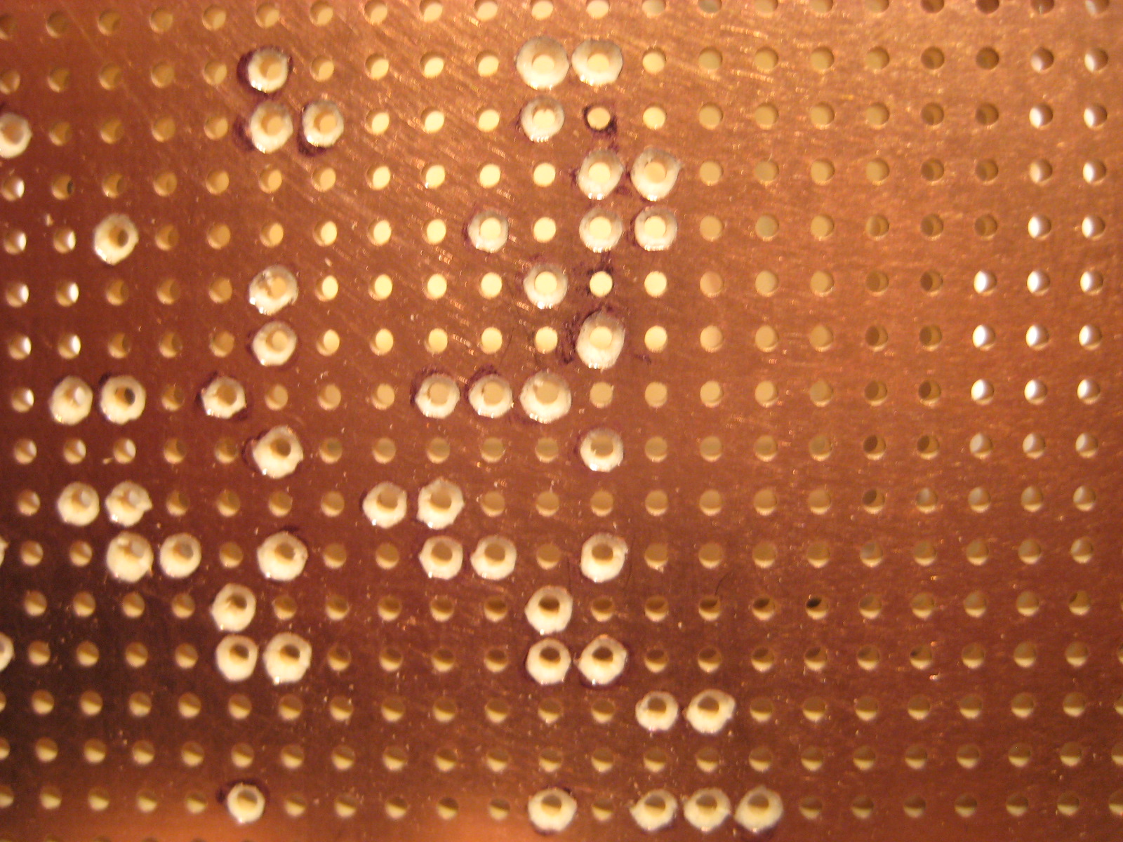
The above board shows how copper is removed from around a hole that must be isolated from ground. Connections to ground are simply soldered to the top of the board. (A 1/8 Inch drill bit works great for the copper removal.)
I have some CNC Milling programs for 7 Pin and 9 Pin Tube sockets, and these will be used for the tubes.
My process involves 1st laying out all of the components on non-copper boards and then taking a digital photo. This serves as a road map for the copper board where I then remove the copper from around holes where the components simply pass through for connection to the underside. This process minimizes finger smudges on the copper surface.

1st Pass for the layout.
Stay tuned and get smart about the politics of a thrice indicted former president.
73's
Pete N6QW
Update 8-02-2023. A Proposed Board Layout.

All journeys start with the 1st step and so here is my first step. As I do with my solid-state projects I tend to build in modules. Chunking a project this way enables/facilitates troubleshooting and fosters experimentation and upgrades. Thus, I see about six modules (boards).
Our IF Module will be steerable and thus will have some relays to move the module between the in's and out's.
The Module containing the most tubes (4) has some logic where the BFO feeds both the Balanced Modulator (Diode Ring) as well as the Product Detector which accounts for two tubes. The Microphone Amp feeds the Balanced Modulator so that makes sense. But the RF Amplifier was stuck there to balance the filament load.
What might make more sense is to include the 1st audio stage since that follows the Product Detector and move the RF Amp to the Audio Amp Board. I have just convinced myself to make that change. That is the value of looking at things for a second or third time.

The Local Oscillator board contains the PTO and Heterodyne Crystal Oscillator. The follow-on board is the Transmit and Receive Mixer stages. Both of these stages use the LO signal.
The Transmit Module contains the Driver and Final Stages and likely would be shielded from other stages. Our last Module will now contain the Receiver RF Amplifier and the Audio Output stage.
Again, we will use a series configuration of the Filaments so that 12 VDC will be the filament supply. So, each Module would contain an even number of tubes.
Our overall size is to fit within a 10 X 14-inch area. The actual Modules will vary in size and might be moved about in the placement to enable signal routing, but this is our starting point.
Just got ask -- when do we start chanting: "Lock Him Up?"
73's
Pete N6QW
Update 8-01-2023. A Big Mistake!

This was an earlier Big Mistake! Above is a solid-state version of the Heathkit HW-101 that just sort of grew from a couple of boards to something that was over 4 square feet of stuff. This was a tri-band version but used all of the frequency elements including the filter, heterodyne crystals and even a PTO from a Ten Tec Model 540.
Here was the mistake, I never thought how the final build would be packaged. This breadboard was not easily moved around. It took me six weeks to finally get it in a box. The final size was 12X12x6 -- a half cubic foot. Not easily transported to the field.
Thus, our lesson from the past that needs to be looked at closely for our 6BA6 radio. As a challenge it should be no more than 10 inches wide and about 14 inches deep. Keep in mind the need for air circulation and cooling. With 14 tubes the filament load alone is 12 (volts) X 2.1 (amps) = 25.2 watts. Add in the plate current and it is like sitting on a 35-watt light bulb. Not enough to make toast but warm enough to think about air circulation.
Solid state affords us the luxury of mounting in any direction --tubes are better vertical.
More noodling.
73's
Pete N6QW
Update 7-31-2023. The Innards of the Transceiver Topology.
At this point we are thinking ahead to the board layouts and the individual boards. History is always a good reference. For this we go back to the typical 1960's/1970's transceiver designs.

In the design above we note several things, the 1st of which is that the signal through the filter is always in the same direction and innovatively grid block (applying a large negative bias to tube grids) cuts off various tubes depending upon whether in transmit or receive.
There is sufficient gain just from the 1st IF on transmit to feed a downstream transmit mixer stage. But more amplification (2nd IF) is needed to feed the product detector.
It does not appear as though there is any post mixer (receive) amplification as the output from the Rx Mixer or Balanced Modulator is simply dumped into the crystal filter. Likely there was no audio filtering following the Microphone amplifier to limit the audio into the Balanced Modulator.
The question is what the differences in signal levels may be from the Rx Mixer and the Balanced Modulator that are being dumped into the crystal filter.
My approach is to insert the Crystal Filter between the two IF stages so that the 1st IF is a post mixer amplifier and if necessary, gain leveling may be applied to the 1st IF amp depending on whether the mode is Rx or Tx.

This approach has worked well with the solid-state topology and will be tested here with the 6BA6's.
Overall gain distribution across the entire transceiver suggests an evaluation. It is not enough to just hook up stages as the end result may be a lot less than something stellar. Just like with solid-state -- too much gain on the front end carries along a lot of noise.
Stay tuned.
73's
Pete N6QW
Update 7-30-2023. The Balanced Modulator.
[If you are in the 50% who do not believe in telling the truth and not doing the right thing, then you are simply wrong! Wake up as you are on the wrong side of a democracy.]
On my 6BA6 SSB Transceiver project, I received an inquiry from a regular blog reader as to why I chose to use a diode ring versus say two 6AL5's connected as a ring? The suggestion had as its basis -- keep it all purely "toobs".

Well, here is my thinking on the matter. I have three working KWM-1's, and each has three 6AL5's used for AGC and ALC (read that is 9 tubes). I have found these to be a weak link as more than one has failed! So not a GOOD experience with the 6AL5. Secondly this adds to the filament load, and this does deviate from a 6BA6 only tube radio.
Another piece of evidence is that both the KWM-1's and the KWM-2 I have employ the diode ring and not another set of 6AL5's. Collins had a good reason not to use them and so I guess I do too!
(I even replaced the 1N34's in a 5th KWM-1 I had and that was a most challenging event. Imagine trying to find four matched 1N34's -- I spent a small fortune on purchasing a 25-piece lot.)
So, the Diode Ring it is (just like the Collins).
I guess the 6H6 could also have been suggested for use versus the 6AL5 as this was a common tube found in many upscale radios of the 1940's.

The schematic on the right is to show the more modern symbology for the diode. This is an octal socket tube -- read a big hole in the chassis! OK BTE's here is some learning for you.
73's
Pete N6QW
Update 7-29-2023. 6BA6 IF Stage.
But 1st a bit of Tribal Knowledge about Guiding Principles. In all things 1) Tell the truth and 2) Always do the right thing. For some reason about 50% of Americans no longer believe those principles. Regrettably that 50% all seem to be of one political party and follow a cult. The Great Republic is in decline.
A starter IF stage (From the SW-100 Series) is shown below.
.png)
Of note the 47 Ohm cathode resistor is part of the manual RF Gain Circuitry. In our design the output from T3 is relay steered to either the Product Detector on Receive or the Transmit Mixer on Transmit. But a bit of care here as this stage if manual RF Gain is applied it must be bypassed on transmit to provide a different gain level between Rx and Tx. This affords possibilities for AGC and ALC implementation.
Stay Tuned.
73's
Pete N6QW
Update 7-28-2023. The 6BA6 BFO.
The BFO circuit below is a "lift" from the SWAN SW-100 Series transceivers. Essentially two outputs are taken from the 6BA6, one from the Plate to the Balanced Modulator and the other from the Screen Grid to the Product Detector.

Considering the board layout, I can see the Carrier Oscillator being included on a board along with the Balanced Modulator and the Product Detector. This would require some relay steering to the rest of the transceiver circuitry but keeps the BFO leads short. Possibly some shielding of this circuit would be required to prevent BFO Leakage into the IF stages. An item to put on a to be evaluated list.
It is important to note about signal levels. The Balanced Modulator is a Diode Ring and so we should look to somewhere between 1.414 Volts PTP to 2 Volts PTP which is 7 dBm to 10 dBm as the level of the BFO signal.
The Product Detector would be a Triode connected 6BA6 and the 1st Audio stage would likewise be a Triode connected 6BA6.
73's
Pete N6QW
Update 7-27-2023. Sample Oscillator

This is a sample of a 6BA6 Crystal Oscillator (40M), as found on the Internet. Our 19.8 MHz crystal oscillator would look similar. But I share this photo to principally show how it was built.
Essentially this JA Ham (the builder) used Manhattan style construction, and this has worked well for him. Importantly a short direct connection to the ground plane at RF is very important. But this also serves to anchor the tube socket to the small sub-chassis. My approach likely would use single sided copper vector board where I mill out the socket penetrations. But lacking a mill his approach as shown in the photo is excellent.
Below is a view of a Diode Ring DBM as used on the LBS Transceiver project. This would be the template for the DBM used in the 23 MHz LO, AND the Balanced Modulator

.jpg)
Alternate way of building the Diode Ring.
Note the Carrier Balance Control. (Yellow Trimmer)
Likely you need to catch your breath and me too!
73's
Pete N6QW
Update 7-26-2023. The 23MHz LO.
Since we have made the choice of using a 9 MHz IF and the band of choice 20M, that places the LO at 23MHz. I can't tell you how many 23MHz LO's I have built using the Si5351. I can do it in my sleep with my hands tied behind me.
But this radio will not use the Si5351, and we have added to the complexity by incorporating a PTO from a Collins KWM-1 as the main tuning element. We added still another layer of complexity as the PTO operates around 3.5 MHz whose 4th harmonic is in the 20M band. We have conditions that are ripe for Unwanted Mixing Products (UMP).
My thoughts have turned to network filters to cutoff any harmonics or restricting the Band Pass of the actual 23 MHz LO.

Above is a block diagram of a 1st pass at creating a "clean" 23MHz LO which should not see the 4th harmonic of the PTO slipping through the BPF. The LPF has a deep null at the 2nd Harmonic.
For the BTE's the PTO output is passed through the LPF so that any harmonics are suppressed. The PTO is injected into the Diode Ring DBM where it is mixed with the Crystal Oscillator (19.8MHz) and that produces sum and difference frequencies. The difference is 16 MHz and that is easily rejected by the BPF whereas the sum frequencies pass through the BPF filter to the Transmit and Receive Mixers.


The Fc is just above 4 MHz, and the second harmonic is nailed at 7 MHz.

The 23MHz BPF

The Output Plot Following the 23MZ Band Pass Filter past the 2nd Harmonic.
Thus, we have an approach to deal with the generation of the 23 MHz LO. Not mentioned earlier will be a tuned output on the 19.8 MHz crystal oscillator so that harmonics from that source are not "cause celeb" for an unwanted mixing product.
Added NOTE: R1 in the diagrams are for simulation purposes and not a part of the hardware build when installed in the radio.
73's
Pete N6QW
Update 7-25-2023. How to Do It. (The does not involve Mary Jo or the back seat of a 57 VW Beetle.)
If you have followed the sojourn so far, likely you are wondering is this chaos or a real plan. It is a real plan and just to recap:
- The design objectives have been stated. The same tube in every socket, albeit some will be triode connected pentodes. A single band (20M) and QRP power levels. Block diagrams have been developed.
- Integration of an available KWM-1 Collins PTO as the main tuning mechanism.
- The IF is 9 MHz and will be both USB and LSB and a novel use of module steering of the IF circuits.
- Series and parallel connection of the tube filaments (12 VDC) and a plate supply of 250 volts. This now becomes a significant parallel development issue as to how to supply power to the radio.
- Use of published circuitry for the many subcircuits. (A lot of borrowing here AKA lifting from SWAN Radios.)
- We will employ a prototype development bread board to test circuit configurations prior to finalizing the design.
- We have employed a "noodling" process so far and the soldering iron has remained off.
A word about the power supply and the filament requirements. The 6BA6 requires 6.3 Volts at 300 milliamps. For 7 branches (fourteen tubes with two tube filaments in series) that comes to 7 X 0.3 = 2.1 Amps.
Amazon is your friend, and I bought this power supply that is adjustable from 3 to 12 VDC with sufficient current to run fourteen tubes. The supply can do 5 amps! This is the supply I will use with the bread board fixture. The cost is under $20 and has an LED display.

I would think that many of the blog readers at this point are asking why he is screwing around with tubes. Well, friend it is the design process that is the real thrust and not so much the specific use of devices. I bought 15 tubes for $2.68 -- too good to pass up an opportunity to build something!
It doesn't matter if you are working with tubes or transistors, the process is the same. Start with an objective, collect data and information, evaluate the suitability of various approaches and finally identify challenges and opportunities. All this was done without one whiff of solder smoke!
This is fun. Indeed, this was a struggle in my youth: Ham Radio or Mary Jo. Now it is all radio stuff.
73's
Pete N6QW
Update 7-24-2023. Borrowing (A polite form of "lifting") from others.
A good friend and avid homebrewer typically will start any new transceiver project by employing design elements from the VU2ESE Bitx project and sub circuits from W7ZOI. Perhaps additional input may come from Doug DeMaw's designs and/or Frank Jones which will find their way into the finished project. There is good cause for this approach as the foundational base is proven and well known.
Being a maverick, I designed a SSB transceiver in 2022, that had as a design goal to use no Bitx Circuits, no TIA Amps, no EMRFD and no Facebook groups. I was successful in that endeavor. The rig (P3ST) has but 7 discrete transistors.
Todd, K7TFC, and his company Mostly DIY RF on August 26th will be releasing this rig as a kit known as the P3ST.
At one-time in the 1990's I was fortunate enough to have about a 2-hour rag chew with Herb Johnson (W6QKI SK) founder of Swan and Atlas Radio. I asked about his designs, and he answered with the term Value Engineering. Essentially his designs were minimum part count yet with good performance. Since most of the early Swan designs were vacuum tubes, I often look to those designs much like my friend who is anchored to VU2ESE and W7ZOI.
Thus, I will be borrowing some of Herb's work as I develop the 6BA6 SSB Transceiver project. Below is a partial schematic from a SWAN 240. Note the last IF stage is a 6BA6 and that feeds a product detector which is one half of a 12AX7 which I am substituting a triode connected 6BA6. This even has AGC, where I will use 1N4007 diodes.

If you pull up the schematic for the SWAN 350, the Carrier Oscillator is a 12BA6 (I will use a 6BA6).
Thus our "borrowing" of circuitry will move the prototype process along quite nicely and we will be stepping on the path made by others.
73's
Pete N6QW
TIT
Update 7-23-2023. The Transmitter Block Diagram.
The tube type transceiver is much different from a solid-state type of transceiver in that the advantage of broad band untuned circuits simply is not fully there with the tubes. Thus, we tune, peak and load the radio as we QSY across the bands.
Keep in mind it is watts to the antenna and how well you hear signals that really counts. Both approaches provide that end result albeit one approach simply tunes across the band.
Some of my friends would argue that the solid state is simple. That is an undeniable fact. But those same individuals may argue against DDS and PLL LO's in favor of analog VFO's with solid state radios. Truly a conundrum!
What could be more fundamental and back to our ham radio roots than a tube type transceiver which uses an analog PTO and a crystal BFO. Certainly, with tubes you would really have to know how each function works. Using common circuits on both transmit and receive is a challenge to understand how things work down to the component level. So, taking this journey is a real learning experience.
Most of the blocks in the project are well known as to the detailed circuitry and we have an array of options on how to implement the individual blocks.
But one block may be classed as aspirational. That block is the one called the 6BA6 Mixer Oscillator. The premise for this goes back to the times when QST was really a ham's magazine and not a catalog of offshore radios. One consummate QST technical guy was Lew McCoy. He penned a QST article regarding the use of a Dual Gate MOSFET (40673) that was a combined crystal oscillator and a mixer stage. In essence it was a one device signal convertor.
I ask why we can't do that function with a single 6BA6. We would ask that this 6BA6 would take the KWM-1 PTO output (3.5MHz) and mix that with a 19.7 MHz crystal oscillator signal to produce a 23MHz LO signal. Yep, do that whole process in one tube.
The fall back is a single 2N2219A Crystal Oscillator outboard of the 6BA6 -- but that would be a blemish on the whole project. Another still is to add one more 6BA6 as a Crystal Oscillator. If any reader has seen a combined Mixer Oscillator in a single pentode --shout out to me.
Transmitter Block Diagram
We have a total of 9 Tubes in the Transmit chain. Not Shown are tuned networks and filters to ensure the output is clean and no spurious signals. I am hopeful of at least 3- or 4-watts PEP.
Five of the tubes/circuits are also common to the receiver with the other four tubes being used as the Microphone Amp, Transmit Mixer, Driver and Final Amp.
Substantial thought will be involved in what circuits go on what boards to minimize the wiring. The Transmit Mixer and Receive Mixer on the same board makes sense. Another is the Balanced Modulator and the Product Detector and ditto for the Microphone Amp and Audio Amp.
73's
Pete N6QW
Update 7-22-2023. The Receiver Block Diagram.

Our goal was fourteen 6BA6 tubes for the whole transceiver and just the receiver shows some ten tubes. Well, if we look closely, we see the IF Module has two tubes that would be steered into the transmit path and the LO has two more tubes that likewise would be used on transmit. Finally, we have the BFO that is also in the transmit chain. That comes to five tubes and the four others gives 9 tubes in transmit.
Some hidden mine fields here and one is the LO. For those who listened to SolderSmoke Podcast #247 you hear Bill describe the problem of hearing the 6th harmonic of his VFO on the 15 Meter band. Well, the 4th harmonic of our Collins PTO (3.545MHz) surprisingly is at 14.180 MHz.
So how to cure that? Well, one approach is to include a low pass filter between the Collins PTO and the 6BA6 Oscillator/Mixer stage. The additional remedies include a BPF following the mixer so that only signals in the 23 MHz range would pass. Finally, if we have a stubborn 4th harmonic, we can include a trap in the LO output.
It is well to mention that there were no intermediate circuits in Bill's VFO -- aside from a VFO amp stage. Our LO has a mixer stage and the additional filtering.
Not shown is the steering relays for the IF Module nor how the Receiver Mixer and Balanced Modulator would be on the same 4X6 Circuit Board and that the Product Detector and Transmit Mixer would also be on the same PCB.
Stay tuned.
73's
Pete N6QW
TIT
[Google analytics are really cool as they let me see from what countries are the blog readers. A huge shout out to the 12 Blog readers in Croatia. Back in my home state of Pennsylvania, I knew some Croatian families who emigrated to the US following WWII. They came to work in the coal mines and steel mills. What I mostly remember were the YL Croatians that went to my high school. Real knockouts! The Ukrainian YL's --same story.]
Update 7-21-2023. An "A" Change. Frequency Scheme and IF.

My original plan was to utilize a 455 kHz Mechanical Filter (Collins). Following with keeping it simple, I have now migrated from a dual conversion to a single conversion design. The IF I have chosen is 9 MHz and this has made life a lot simpler. [9 MHz filters available from Mostly DIY RF.com ]
The shift is because it was difficult to find heterodyne crystals to work with the 3.5 MHz PTO and 455 kHz IF.
The BFO crystals 9.001500 and 8.998500 MHz are available from Digi-key. Using this scheme two stock computer crystals at 19.6893 and 19.8 MHz respectively, provide 20M coverage from approximately 14.150 to 14.350 Megahertz. [Mouser for the two stock computer crystals.]
Let's do some fun math. We are placing the LO (a mix of the PTO, 3.445 to 3.545 MHz, with the 19.6893 and 19.8 MHz Oscillator crystals) above the operating frequency. This nets 23.1343 to 23.2343 tuning range with the 19.6893 crystal. Now since we are using an LO above the operating frequency there is sideband inversion. Thus 9.001500 MHz BFO gives USB. A small subtraction looks at a range of 14.132800 to 14.232800.
The second crystal at 19.8 Megahertz results in 14.243500 to 14.343500 Megahertz. Yes, we miss about 12 kHz between the two ranges. I believe there may be a crystal that would overlap the ranges but would miss a few kHz at the low end. I will check that out.
To avoid some potential birdies and unwanted mixing products I will include a BPF following the LO.
Yes, you all probably are wondering about a block diagram. That will be coming forthwith now that we have nailed down the frequency scheme.
TIT -- another indictment soon to be initiated!
73's
Pete N6QW
Update 7-20-2023. IF Module (Steerable)
Sourdough bread starts with sourdough starter. For our IF Module I looked at an IF Amplifier stage as found in the KWM-1. The tuned circuit L16 would be replaced with the Mechanical Filter and steering relays integrated into the input and output of the module. Much work is needed to re-design this stage, but it gets the process going.

This not a plug and play but a starting place.
TIT!
73's
Pete N6QW
Update 7-19-2023. The 6BA6 as the Final RF Amplifier.
The pentode was invented in 1926 and will soon see its 100th Birthday. So indeed, an OT.

There are some generalized considerations when applying any tube or transistor as a final RF amplifier. The very first is the class of operation. The final must be linear to produce a signal without distortion. The ultimate class of operation is Class A, where the current flows 100% of the time and a lot of heat is generated, but surely linear. Class C is best for CW and something not suitable for linear operation. In between is Class B and some subsets are Class AB. This is our goal as it provides linear operation without the heat, so AB it is.
The duty cycle of SSB (peak envelope power) lets you take a horizontal deflection tube like the 6DQ5 that has a 17-watt plate dissipation to produce in excess of 100 watts PEP.
Thus, the plate supply, bias point, idling current and drive level are some of the critical factors to consider in our final RF amplifier design.
To get a couple of watts at 14MHz we likely will need to have somewhere around 100 to 200 milliwatts of drive. For 3 watts output with 100 milliwatts of drive we would need about 15 dB of gain. If we could get 200 milliwatts of drive that drops to about 12dB. Thus, optimizing the Driver stage is also of import.
Again, the prototype breadboard will be key in the full development of the Driver and Final RF Amplifier stages.
An intriguing option is to arrange our 6BA6 in a grounded grid amplifier configuration otherwise known as a zero-bias circuit. It takes more drive power but reduces the possibility of oscillation. Watch this video from W1GV.
Hey Tuberville, get off the stage your time is up. Lordy another indictment in the wings complete with tapes. TIT.
73's
Pete N6QW
Update 7-18-2023. The 6BA6 as an Audio Output Stage.


This is a starting place just for reference.
I don't think I have ever seen an audio output stage that uses a 6BA6. There are some pieces of information that suggest that its use in that socket actually might be a good idea.
The 1st indicator is that its plate dissipation is greater than 3 watts. So, one or two watts of audio output is not in conflict with the 6BA6 capabilities.
The second piece of data is that the 6BA6 is a remote cutoff pentode -- an ideal attribute for application of AGC. But a search of the Internet and Wikipedia (you know how trustworthy that can be) reveals the following. The remote cutoff is the best of the pentodes for power output and signal handling.
Remote-cutoff, variable-mu, super-control or variable slope pentodes handle much greater signal and bias voltages on the control grid than ordinary pentodes, without cutting off the anode current. The control grid of the variable-mu pentode is constructed so as to result in a given incremental change of control grid voltage having less effect on change of anode current as the control grid voltage increases negatively relative to the cathode.[7] The control grid often has the form of a helix of varying pitch.[8] As the control grid voltage becomes more negative, the amplification factor of the tube becomes smaller.[7][9] Variable-mu pentodes reduce distortion and cross-modulation (intermodulation) and permit much larger amplifier gain.
So, the next task is to flesh out the component values such as the plate load as we will need to match the audio output transformer to that load. The cathode resistor likely is 68 Ohms and that would be bypassed with a 47 Ufd electrolytic @50 volts. The output transformer would be connected between the Screen Grid and the Plate. The input Grid resistor likely 220K. Perhaps even some grid block circuitry on transmit.
[Here is an answer from the oracle at ChatGPT AI.
Designing a vacuum tube audio output stage using a 6BA6 vacuum tube and a transformer output involves several considerations, including the tube's characteristics, operating parameters, and load impedance requirements. Here's a suggested design for a single-ended class A amplifier using a 6BA6 tube:
Tube Selection:
- The 6BA6 is a pentode tube commonly used in RF and IF amplifier circuits. It can also be employed in audio applications with suitable operating conditions.
Power Supply:
- Determine the power supply voltage based on the tube's maximum plate voltage rating. For the 6BA6, a B+ voltage of around 200-250 volts should be suitable.
- Implement an appropriate power supply circuit with sufficient filtering to provide a stable DC voltage.
Biasing:
- Establish a suitable bias point for the tube. A fixed bias scheme can be used, which involves applying a negative bias voltage to the control grid (pin 1) relative to the cathode (pin 3).
- Calculate the required bias voltage based on the desired idle current and the tube's characteristics. Aim for a bias point that keeps the tube in class A operation.
Load Impedance and Transformer Selection:
- Determine the desired load impedance and the desired output power level. This will help determine the turns ratio of the output transformer.
- Choose a suitable audio output transformer with the desired turns ratio, primary impedance, and frequency response characteristics.
- The primary impedance should match the tube's plate impedance to ensure efficient power transfer.
Circuit Design:
- Connect the tube in a single-ended class A configuration, using the following connections:
- Connect the plate (pin 6) to the primary side of the output transformer.
- Connect the cathode (pin 3) to the output transformer's center tap (common connection).
- Connect the control grid (pin 1) to the negative bias voltage source.
- Connect the screen grid (pin 4) to the B+ voltage.
- Connect the suppressor grid (pin 2) to the cathode.
- Include appropriate bypass capacitors for the cathode and screen grid to stabilize the operating conditions.
- Add grid stopper resistors to prevent parasitic oscillations.
- Include coupling capacitors to couple the output of the 6BA6 to the primary side of the output transformer.
- Connect the tube in a single-ended class A configuration, using the following connections:
Output Stage Wiring:
- Connect the secondary side of the output transformer to the speaker or the desired audio load impedance.
- Ensure proper grounding and shielding to minimize noise and interference.
Please note that designing a vacuum tube circuit requires a good understanding of tube characteristics, safety precautions, and circuit design principles. It is advisable to consult tube datasheets, reference books, or seek assistance from experienced tube amplifier designers to ensure a successful and safe implementation.
Got it.]
BTW our plate dissipation means we likely could coax about 2 to 3 watts of RF out of the final amp.
Hey Tuberville, your 15 minutes of fame are over! Release the promotions, get off the stage and slink back to your seat.
New indictments coming for DJT. Get your TIT hat which is available on Amazon.
****
Update 7-17-2023. IF Amplifiers.
A brief tour through the Internet has provided us some good starter IF amplifier circuits. These circuits will need some prototype development but indeed a great starting point.
The prototype development must include the addition of the SSB filter which currently is planned as a 2.1 kHz Collins Mechanical Filter. One does not simply drop the filter in between two Ferrite core matching transformers. The impedance of the Mechanical Filter may be as high as 50K and not something around 500 ohms or less as you might see with commercial or homebrew Crystal Filters.
I struggled with this problem when I built the KWM-4 which you can see on my QRZ.com page. For those who may not know, I designed and built a solid-state version of the Collins KWM-2 complete with the Collins Mechanical Filter. So, this is not my first experience with the problem.


Output Side
I will also evaluate the concept of having a 6BA6 IF Module (2X 6BA6's and the Filter) as a steerable module a concept used on the P3ST SSB Transceiver.
Instead of having signals passing bi-laterally through the filter the signal is always passed in a single direction with the inputs switched into the module depending on the mode, id est, transmit or receive. There are some distinct advantages to such an approach and involves just a few good quality communications relays.
The KWM-1 uses the bilateral approach through the filter, and I think adds a bit of complexity with regard to signal isolation. In the steerable module approach the input side would see the receive mixer and the output side would see the product detector. In transmit the input side would see the output of the balanced modulator and the output side would see the transmit mixer.
Since we have already discussed using 4X6 copper PC boards, the steerable approach enables grouping circuits on such boards. As an example, one board could have the receive mixer and transmit mixer and common threads for these two circuits is an HFO and LO. Another board could have the balanced modulator and product detector with a common thread being the BFO. You got it -- minimizing the routing of RF signals all over the chassis.
Hey Tuberville, time to man up and sign off on the promotions.
Update 7-16-2023. Triode Oscillators.
In a previous post we showed how to connect our 6BA6 pentode as a triode. We must do that first before applying that tube as a triode oscillator.

While the example I found for a modified Pierce oscillator shows a 6J5, there is no reason why the triode connected 6BA6 would not work. But we must 1st follow the arrangement for the 6BA6 as a triode.
Undoubtedly there will be some tweaking of this circuit for best performance but this is a starting place. That tweaking is a result that in one case the BFO crystal is 456.8 kHz and the HFO crystal would be 18.2 MHz and many circuits simply will not operate over that wide of a frequency range with the same circuit constants.
Again, the use of a prototype development breadboard facilitates such tweaking.
When undertaking such a project like an all tube SSB Transceiver there are certain underlying assumptions and the very 1st of those is the power supply. My assumption is that the filament supply will be 12 VDC (series parallel connection of filaments) and the plate supply will be 250 VDC.
Hey Tommy Tuberville, I used chatGPT AI to generate your curriculum vitae. I found that all of your claimed attributes about being a team player are inconsistent with your actions regarding military promotions. Have you read your CV?
73's
Pete N6QW
Update 7-15-2023. Pentodes Converted to Triodes.
The above link shows how to connect a pentode to become a quite excellent triode. You have these two extra grids, and the task is how to connect them? The other point is why do it?

Hey Senator Tuberville, here is what a 25-year-old 0-3, USN looks like (Navy Lieutenant). The scenes on the beach are in a forward combat zone vintage 1965, Chu Lai RVN. Oh, that's right you never served! In 1965 what were you doing?
We now are starting to add meat to the bones of our 6BA6 SSB Transceiver. At least three of the sockets will have triode connected 6BA6's. In my next post I will try to scope out the component values.
A piece of tribal knowledge. Build a test fixture dedicated solely to prototype circuit development as this enables you to work out the kinks and aberrations. It also gives insight into how to optimize the actual physical hardware -- no Manhattan construction here. The plan is to use 4X6 inch copper PCB boards and cut out the tube sockets using my CNC mill. The prototype is a key aspect in using the Mill for the socket installation.
******
Update 7-14-2023. Senator Tommy Tuberville, you never served, thus you have no clue about the impact you have created not only to the men and women in uniform but to their families. You are affecting our military readiness! Bluntly speaking you are simply wrong, and you should have stuck with the footballs.
I know personally when I got promoted early from a Lt(jg). to Lt. USN, it was a big deal and opened up opportunities for an increased responsibility in job assignments. Two full stripes on my uniform were a huge chick magnet which I also saw as a fringe benefit!

Possible 6BA6 Mixer Stage!
Potential for use as the Rx or Tx Mixer, perhaps even a Product Detector.
Circuit values shown are a 1st approximation and starting point. Input #2 would be the LO, or BFO input (as would the case with a product detector).
We would also need to evaluate Tuned Circuits on the output side so that we are only passing the desired mixing products.
I see the potential of steerable circuits and Broad Banded, Band Pass Filters.
********
Update 7-13-2023. It is imperative you have at least one vacuum tube radio transceiver!
We are living in dangerous times. Two guys with nuclear capabilities, pose a serious risk to the US. Kim Jong and Vladimir are of much concern to the world order and should they pull the trigger your Icom7300 will be like Trump -- TIT. Only this time Transceiver Is Toast. The EMP from a nuclear explosion renders solid state equipment useless, whereas vacuum tube equipment simply skates on by.
Acquire or build a tube rig to keep on the air when the big one hits. (Note that is not if, but when.)
Update 7-12-2023. Tube Line Up for the 6BA6 Transceiver.
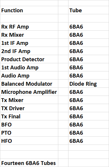
The goal is to utilize the 6BA6 tube in virtually all of the sockets. In some instances, it may not be the optimal choice for the function but nonetheless will work. BTW the Plate Dissipation of a 6BA6 is 3.4 Watts.
This approach follows what the Germans did in WW II with their field radios where every function was the same tube and neatly packed inside each radio was a single spare tube usable in any socket.
73's
Pete N6QW
Update 7-11-2023. A Frequency Scheme using a Low IF (455 kHz). (TIT).
If we use a dual conversion system with a 455 kHz IF and our 3.445 to 3.545 MHz KWM-1 PTO, then a 2nd Mixer Stage would have an input of 3.9 MHz to 4.0 MHz. The math: 3.9- 3.445 = 455kHz and 4 - 3.545 = 455 kHz.
Thus, tuning a range of 14.2 to 14.3 MHz we would need a HFO at 10.300 MHz. The math is as follows: 14.2 - 10.300 = 3.9 MHz and 14.3 - 10.3 = 4 MHz.
Or with a case of sideband inversion the HFO is above the operating frequency so that:
Thus, 18.2 - 14.2 = 4.0 MHz and 18.2 - 14.3 = 3.9 MHz with a dial tuning in the reverse direction. In the Collins scheme they actually divide the 18.2 by 2 and so the crystal frequency is 9.1 MHz and then the HFO uses a frequency doubler for the injection.
Adafruit sells a clock oscillator that could produce any of these frequencies and costs about $8. Ditto for QRP Labs and that cost is about $18. In essence we would need a crystal for each 100 kHz of coverage.
[This is just a 1st look at a frequency scheme and a spur analysis would have to be performed to determine any unwanted mixing frequencies.]
The BFO signal could be supplied by similar clock oscillators.
Thus, the noodling of a tube transceiver has begun. But for those who would not use tubes the same frequency analysis would apply using any SS counterparts.
I am doing tubes mainly because I can and not many others can. It is a lost art! Besides I bought fifteen 6BA6 tubes for less than $9 shipped! The KWM-1 PTO uses a 6BA6.
Pete N6QW
Update 7-10--2023. (TIT = Trump Is Toast sayeth Bill Barr!)
The spare Collins KWM-1 PTO is alive.


The Rev. George Dobbs (SK) essentially the father of the G-QRP Club had a minimalist philosophy insofar as homebrew is concerned. Often, he is quoted as being a One and Done guy! The idea: one evening of work and the project is done. Although the gear was simple (DCR's and one device transmitters) it worked and thus the challenge of something simple, yet it works.
[Editor's note: One and Done can also be applied to Mary Jo and the back seat of the 57 VW Beetle.]
The age of Solid State is all around us but in the old days it was tubes. Immediately the flags go up about high voltage and safety. There is no doubt that is a huge concern especially when you look at ARRL projects from the 50's where safety was not a concern. To wit no fuses in power supplies or keying high voltage supplies and/or no bleeders on electrolytic caps.
But what if you used batteries for the filaments and a parcel of ten 9 VDC transistor radio batteries in series for the high voltage -- then a lot less scary. There are battery type filament tubes such as the 3S4, 3Q4 and the 3A4 that can deliver enough power to be heard. A single 3A4 can produce 700 milliwatts and a pair easily greater than 1 watt!

This indeed is a One and Done project! Also note not a lot of components and likely more juice to the antenna than a Michigan Mighty Mite -- the bonus a Pi Network Output!
Spotted in a medium sized CA town, an answer to the MAGA Crowd. I was aghast at the printing until it was explained to me that TIT = Trump Is Toast as decried by Bill Barr!

Where is the Fuse, ARRL?
73's
Pete N6QW