Update 12-31 2023 Rounding Out the Year
Update 12-31-2023. The last day of 2023. What better way to finish the year than to think about older boat anchors and how they can be rejuvenated to work on today's bands.
Spending a better part of each day at the hospital where the only TV service is standard TV with the stupid quiz shows and of course HGTV, you basically go nuts. Quite often the OL is asleep and so not much to do but think about how to replace the drifting and non-linear Analog VFO's in boat anchor radios. No time to build stuff but lots of thinking time.
One of my favorite radios is the Hallicrafters SR-160 (right along with the SR-150 which I don't have). But it suffers from a drifting and NON-Linear VFO.
Based on my success with the Triton II, I asked why can't we do the same with the SR-160 (or National NCX-3 or even a SWAN 240). Well I think it can be done!
The SR-160 used the old trick of a higher frequency VFO @ 9 MHz with a 5.2 MHz IF. Subtract the IF from the VFO and you get 75/80M LSB and the add the two gives 20M USB. Now this is where the SR-160 is pretty slick -- for 40M they light off a 3.4 MHz heterodyne Crystal Oscillator and mix that with the VFO to give 12.4 MHz. Subtract 5.2 MHz and you get 7 MHz LSB

The frequency info on the photo above is what is needed for the input to the Arduino. There is a regulated +150 Volts which feeds the plate of 1/2 of the 6EA8, V17B. The first modification is to disconnect that +150VDC from V17B source and tuck the wiring away. Returning to stock is a pretty simple chore. The filament load remains balanced but the tube is inactive!
I would feed the signal from the Arduino/Si5351 module into the Grid of V17A (the other half of the 6EA8). Likely some matching would be needed so that is an item to be further evaluated.
Thus my Arduino/Si5351 would always tune the same 500 kHz segment but the magic comes in as to how the band data is displayed on the LCD. Pretty to easy to do as this nut was cracked in the Triton II.
The one function not retained with the original radio circuitry is the RIT. But there are some clever guys (not me amongst that group) who have figured out how to incorporate RIT into the sketch so I will try to track that down. Then all functions would be available in a remote box.

I can just see the remote box now with say some sort of really Big Knob, like off of a National Velvet Vernier as the main tuning knob sitting next to a cool blue 16X2 LCD and a $5 Keypad.
Happy New Year!
Trust me when I say good health is everything. Stay healthy by keeping up on all vaccinations, get regular checkups and eat healthy. Cheetos is not one of the basic food groups -- neither is Beer!
73's
Pete N6QW
Update 12-30-2023. Fifty six years ago this day I made a life altering decision. It was something carefully orchestrated so that I would achieve maximum economic benefit and hopefully propel me on a new path of life. Like in the Tale of Two Cities -- it was the Best of Times and the Worst of Time.
Just about six months prior to December 30th, I had completed my four year commitment to the US Navy and survived two trips to South Vietnam. With that behind me, nothing would be difficult -- well I had thought that would be the case. When you are in your Mid-20's I guess that could happen.
To end the suspense, December 30th, 1967 was the day I got married. The economic part. I could claim the XYL as a dependent for that tax year. But like they say about alimony -- it is not free. So on this day, we are observing #56 at the Hospital where the XYL (OL) is recovering from one of those female maladies. Remember The Tale of Two Cities?
BTW I could not get the Board Manager to load the Seeed Studio XIAO RP2040. But that was on an IDE 1.8.5, but it did take the Raspberry Pi Pico 2040.
I hate those videos where you are shown three mouse clicks and all falls into place -- well it didn't in this case! The Board Manager could not find the Seeed XIAO RP2040
There is a limitation of GPIO Pins which makes this not Suited for some of the Color TFT's unless you can use a board expander. But then that defeats the really small size, nor 7 pin Keypads. But OK for LCD's using I2C and an encoder and a few switches.
Happy New Year,
Pete N6QW
Update 12-29-2023, Just a few days left to take advantage of the sale price. Not only a super deal but sports the latest technology!

This is not an Arduino Uno R3 but the seed studio RP2040 (Raspberry Pi Pico Chip) Micro-Controller Unit that runs K7TFC's P3ST. It is a Dual Core ARM Cortex device that can run at 133 MHz which is 8X faster than the Uno. This device can be programmed with the Arduino IDE or Micro-python. Available through Digit-Key @ about $6.
At that speed this has possibilities for running an SDR Rig and doing the Fast Fourier/Hilbert Transforms heavy lifting. Think of my Fat Finger Thumbnail and yes, that is the size. Find this in the photo group below and you can see Todd's thumb and the MCU. It is also about half the size of a Si5351.
This
From This

Happy New Year & 73's
Pete N6QW
Update 12-28-2023. The P3ST Transceiver is available for sale. Todd, K7TFC is now taking orders and the introductory sale price ends on January 3rd, 2024
https://www.mostlydiyrf.com
Aside from the thrill of originating the P3ST design over two years ago, today I see an opportunity for anyone purchasing the kit, as a chance to tinker with hardware. The Modular approach with plug-in boards screams experimenter's platform. Or better still by chunking the circuits into blocks to actually learn how a SSB transceiver can do its magic!
If you smoke a module--an easy replacement. No doubt, some of the "noobs" and even OT's will smoke a board or two but not a total disaster. Todd's kit was designed with DFMA (Designed For Manufacturing & Assembly) in mind as the cure is simply plugging-in a replacement module.
Todd has made many improvements to what I cobbled together and offers the complete kit. BUT he also is selling individual modules for those who would like to roll their own. Shown below is the kit and the individual modules.

For those with less than "keen eyes", the parts needed to prodiuce RF are small in numbers. The potential of three bands is also a bonus!
Todd, K7TFC has done an amazing job of translating my design to the circuit boards and to integrate them on to a Motherboard. I think the Arduino comes pre-programmed so those of you with two left feet can make this kit play literally out of the box.
Frankly, my P3ST project had as a goal to not use Bitx Circuitry, to not use EMRFD circuits and to not borrow from Facebook groups. It was to be a new design and a new way of doing things by employing relay steering. I was successful and in a large part (aside from the colorful boards) Todd's offering builds on that concept.
Quite honestly I am nauseated by the many projects that simply repackage Farhan's quite excellent Bitx design and that never stray into uncharted territory by experimenting with new hardware designs. The P3ST unequivocally IS a new hardware design.
My original P3ST was somewhat panned by the hackaday crowd because you had to make everything and there were no ready made circuit boards nor bags of parts to be furnished. I also secretly suspect that those who are forever tied to the Bitx literally with their umbilical cords, felt it would be a dishonor to VU2ESE, if something was tried other than his Bitx design. I believe Todd's P3ST kit now removes those fabricated obstacles.
The original P3ST employed 7 transistors with five of those being 2N2222A and the other two a 2N2219A and a IRF510. Yes, with but a few devices you can work the world.
More than several purists when my P3ST was on hackaday, grumbled about the LM380N and the Arduino/Si5351 as not being in the count. To them I say screw you and let's see your design! In essence the part count is low which makes it possible to offer a kit/modules at very competitive pricing.
In
retrospect other than a couple of P3ST's that I know were built my design
never enjoyed even a fraction of the popularity of the Bitx -- until
now. You had to know stuff to build my design and not many hams have a
CNC or my level of hardware building experience. No excuses now with the availability of Todd's kit.
So get off the couch, amble over to Tindie, whip out the plastic and join in on the fun. Get on the link and purchase a really neat rig and keep in mind no LC VFO's to fiddle and fool with. You are on frequency (within 20 Hz) and no drifting.
Happy New Year & 73's
Pete N6QW
Update 12-27-2023. Two Days After Christmas! Bah Humbug!
The OL (old lady) took ill on Christmas and so yesterday I spent 12 quality hours in the ER as they diagnosed and treated a pretty bad UTI. They are keeping her for a couple of days and the additional wait time in the ER -- just like Christmas, no room at the inn (hospital) until 10 PM last night.
Just thinking here ... No one gets discharged from the hospital (unlike the ER) at 10 PM. So, are we in a room where someone just passed away and we are hot bunking it? Sorry but with only 5 hours of sleep -- I may be off on the deep end. In just a few minutes, I go back for another dose (that is like medical talk) of cajoling the OL to take her psychotropic drug cocktail. I actually buy that stuff legally as it is prescribed medications!
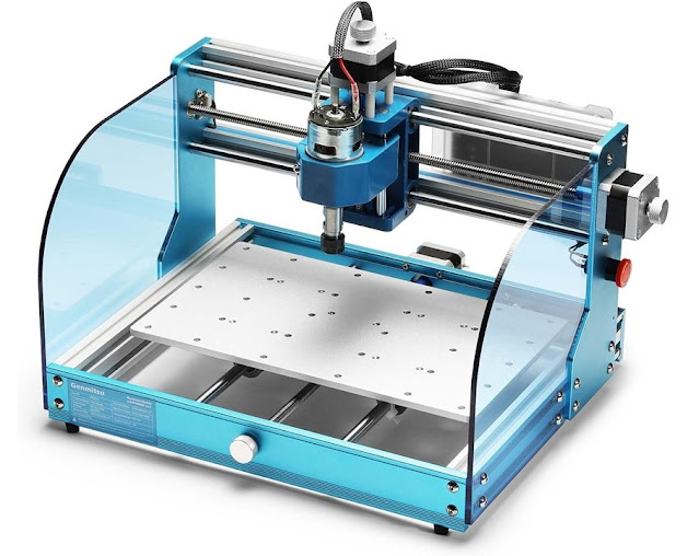
So while I was with the OL, #3 son who is visiting for Christmas further refined and tuned up my CNC machine. When I got home from my half day (12 hour) sojourn at the local ER, he says look what you can do with your CNC.

He took the scrap cutout from the Triton II, keypad and turned it into a pad per hole PC board. The holes are on 0.1 inch centers and the mill head was a four flute 1/32 inch end mill. The pads were cut with an engraving bit. If you buy this stuff from Vector -- get a home loan as you will need it.
But now I have a program where I can "roll my own". You will have to clean up the board from the cat whiskers chaff from the holes/pad cutting but no big deal!
While the purgatory of staring at misery for 12 hours only broken up by looking all of the YL nurses with exotic Tattoos, I did get a CNC Machine tune up and a program to cut pads per hole. I temper this neat board with the thought that this only cost me $250K to send him to engineering school. Remember that home loan thing I mentioned.
The small added bonus! I commented to one YL Nurse that she had some pretty amazing body art which was visible. She shared with me -- the best piece of body art only my boyfriend sees. Now that did break up the boring bed wait a bit, as I imagined what it was and where it was. ER's can be exciting!
Happy New Year and I do hope your Christmas was better than mine. No radio/electronic gifts but did get some nice practical gifts like clothes from the kids. They think I am dated by what I normally wear.
Just before Thanksgiving my #3 son returned from a two week business trip to Germany. While there he bought me a Christmas gift. It is a substantial folding pocket knife made by Walther. Undoubtedly German Mechanical Engineering and Craftsmanship are truly evident in this knife. Thanks Nick!
Happy New Year & 73's
Pete N6QW
Update 12-23-2023. Two Days Before Christmas.
Two Days Before Christmas
And all Through the House
Shack Chaos yes, even the Mouse
There you were looking
No New rig under the tree
Not even a junk Chinese Pixie
You were forgotten this year
Not even the very special beer
Then the thought arose
A thought to all of those
Who stepped on your QSO
All tied in a bright shiny bow
May their Finals get Smoked
Their coax with a pin get poked
But to the kind hams you do know
Merry Christmas with lots of snow!
So that you may get a final look for 2023.
Happy Holidays,
Pete N6QW
Update 12-21-2023. A lot can happen in fourteen years.
A significant thing occurred fourteen years ago, almost to the day (Christmas week December 2009), and that was placing one of my homebrew SSB transceivers on the air.
Following that was my first ever published major article regarding that project. It didn't make the cover of the Rolling Stone but it did make the cover of QRP Quarterly.
Now this was not just any old transceiver nor was it taking a design like a Bitx and conveniently building the exact same circuit for a different band or putting it in a different box. This project was a totally new concept in the use of devices not normally found in ham rigs. It was something other than a 2N3904 or 2N2222.
As often occurs with me, I get these screwball ideas while I sleep. That is the only explanation I have for suddenly awakening and thinking I ought to try this. The major significant aspect of this project was the use of MMIC Devices throughout the whole rig.
20M MMIC SSB Rig
A total of 8 MMIC's (TriQuint AG303-86G, later owned by Watkins Johnson) were employed in the circuit. Three pairs were used in a Bilateral configuration and two more were standalone. Up until that time, I am not aware of anyone having done that.

For those who may not know, the Bilateral circuitry was 1st used in the Cosmophone 35 (late 1950's) and then again in the Sideband Engineers SBE-33. The Bitx was not the 1st Bilateral transceiver!
I received some very useful help from TriQuint in the arranging of the bilateral module thanks to one of their managers who was also a ham. I guess since I was generously using their devices in a ham rig that helped too.
As you will see in the YouTube video, the real shortcoming of this rig was not the MMIC's or bilateral circuitry --it was the drifting, touchy Varactor Tuned Oscillator (VTO) which used a SA612 (NE602) . This was perhaps the very last analog VFO I ever built -- it was awful!
Before publication I replaced the VTO with a Si570 Kit from K5BCQ. What a world of difference that made. This Video shows how a really great rig is ruined by trying to use the old technology with something on the leading edge. POX on analog VFO's!
Now some 14 yIears later we have the Si5351 that does the LO and BFO tasks and along with the Arduino can even turn on the coffee pot and warm up the rig before you even come into the shack. (No kidding on the coffee and rig warming -- I just need to acquire an Arduino with the WiFi ping WWV and then look for a specific time and Boom Hot Coffee.)

In looking back at this project I see that this video had about 4000 views and some of my more recent work like the Triton II Digital Controller got a couple of hundred views. Thus most of my stuff gets very little exposure by what should be a fairly robust audience. Realistically I am not a relevant influence in the hobby nor have a Tik Tok like following.
I will continue to make one or two videos but can see I am like preaching to the choir. So maybe I should just not make any more as my time is limited and the few precious moments I get on the bench are highly prized.
In contrast one of my videos had 39K views and it had nothing to do with cats or ham radio. It was all about stopping water intrusion into my 1995 Jeep Wrangler.
To any who read the blog, I want to wish you the very best of the Holiday Season and hopefully you will find an ICOM IC7300 or FLEX 6700 under your tree on Christmas morning.
73's
Pete N6QW
A post script --video technology sure has improved in 14 years. I did finally build a shirt pocket SSB Transceiver and prophetically ended up living in Thousand Oaks, California. The video mentions the latter two.
Update 12-20-2023. The 5763 Tubes have arrived! I bought four tested/guaranteed 5763's for $8. They arrived.
So OK why the 5763's? Well several years ago I built a linear amp using a pair of 6BQ5's. The circuit was found in the Transistor Radio Handbook (a free download today) authored by Les Earnshaw (ZL1AAX) and Don Stoner (W6TNS) both I think are now SK's.
The authors had two* SSB Transmitters (1967) in the book but no real hi-power SS RF devices were around. So they offered a tube linear amp using the 6BQ5's. It was good for about 15 watts. [* One a phasing rig and the other a filter rig as a part of a transceiver.]
I had good luck with that amp and so let's do it again until I discovered a pair of used 6BQ5's cost about $60 on eBay. Thus the alternative 5763 and I have a spare set.

The data sheet show with about 300 volts on the plate it is good (ICAS) for about 15 watts input in Class C. I am shooting for AB1with a pair and run them conservatively at 15 watts output total. For a Driver I will use a 12BY7A.The drive level to the finals is a couple of hundred Milli-watts.
I will use the 6BQ5 schematic as a starting place and that is found in the book (page 135).

73's
Pete N6QW
Update 12-18-2023. Shout from the Roof Tops and Listen to the Blare of Trumpets. The P3ST is now officially available for sale! Click the link below to Todd's, K7TFC, Mostly DIY RF newsletter. For a short period of time there is a special sale price.
P3ST
The P3ST is an original design from N6QW of a 7 Transistor 20M SSB Transceiver. The design was based on the premise of: No Bitx circuits, No EMRFD and No Facebook Groups! A novel Module Steering Approach results in low device count and multiple use of circuits on both receive and transmit.
The P3ST product offering from K7TFC (Mostly DIY RF) is configurable for 20, 17 or 15 Meters. Talk about arriving just in time for the Cycle 25 Apex!


Using a modular plug in approach it is an experimenters platform just ripe for embellishment and customization. Offered both as a kit and also sold by individual module for those who can tinker.
This indeed this is the Golden Age of Ham Radio!
73's
Pete N6QW
Disclaimer: My only involvement now with the P3ST is that I personally created the original design and prototype. What you see being offered for sale is now all from K7TFC.
Now just to give you a data point to compare Todd's work to mine this was the original prototype.

A second data point: Four birthdays today: E Howard Armstrong, Brad Pitt, Stephen Spielberg and Me. Happy Birthday to all of us born this day. Although Pitt has us all beat -- he has a 30 year old "hot" girlfriend and I think he is eligible for Medicare.

A Red Neck Cell Phone holder! Spotted outside Walmart!
Update 12-17-2023. A Sad Realization is more like it.
December, and its just half over, has been a tough month at the N6QW Laboratories. The XYL has been in the hospital twice and the rest of the month is like follow up medical appointments for her. So there just isn't much time to build and share stuff.
I have met many new people (mostly young health professionals) in the 1st half of this month and to each one I am trying to impart a bit of "Tribal Wisdom" -- Don't get old! The Golden years really Suck!
The realization is that given the current status of the wife, I just will not have the time to complete all of the development of the fully 6BA6 vacuum tube SSB transceiver.
BUT that is not an end in itself!
About a year ago I started building a "Hybrid Wireless Set". That project was about 80% finished and put on hold due to the XYL's health state. There is a reasonable chance that I can finish the remaining 20% and far greater chance of completion than the 6BA6 Rig.

There were some things that needed further study and believe it or not the 6BA6 work has led to a solution for some of the issues in the Hybrid Wireless. The SSB signal (9 MHz) going into the Transmit Mixer a 12BE6 was perfect! Coming out was not so good and I think one of the issues was the Si5351 not being a pure sine wave. Not problem with Double Balanced Mixer's like the ADE-1 but possibly with a 12BE6 tube a different story
Has anyone out there in radio land worked with the 5763? No, we are not floating back to N2CQR's trip to San Francisco and Carol Doda, who in the 1960's was one of the first to have Silicone Implants that might have been 57's or 63's.
The 5763 is a Power Pentode good for about 12 watts up to 50 MHz (Class C). A pair (not Doda) should deliver about 20 watts in AB1. I seem to recall that having the Suppressor Grid not tied to the Cathode is a "good" thing when trying various configurations and that is the case with the 5763.
I am not sure as to the final topology for the 5763's whether they should be grid driven or grounded grid. Any suggestions from those who might know. Each has some pluses in their favor.
The Hybrid Wireless has a LM383 SS audio amp and likely I will change that out to a 12AQ5. (The 12AQ5 is the 12 Volt version of the 6AQ5 and the sub is to make life easier for me with the filament voltage sharing.)
In case you forgot ...
I do apologize for not finishing the 6BA6 rig but am overwhelmed with my other responsibilities.
Happy Holidays and I hope all those who posted a requirement with Santa indeed get that IC-7300 or maybe the FLEX 6700.
73's
Pete N6QW
Update 12-14-2023. The Italian Language has some magnificent words and one of them is "Basta". Literal meaning Stop --enough!
So, tell me when to Basta the Triton II stuff!
Crank Up the Volume!
My free time is Zero -- for the 2nd time in two weeks the XYL is in the hospital. No electrons for Pete!
73's
Pete N6QW
Update 12-13-2023. A Digital VFO and Controller for the Ten Tec Triton II.
[Scroll to the Bottom More Video of Remote Control Boxes!]
Shown below is my answer to not settling for a crappy drifting LC VFO. This is more than just an LO you find with an Arduino and Si5351. It sits up and barks.
This is mine so let's see yours!
The Keypad selects the proper LO range with Keys 1-5 selecting bands 80-10M. Two other buttons enable step tuning rates of 100 Hz and 1 kHz. The radio can also be up/down tuned with two of the designated buttons and the remaining two buttons will let you select a +10 kHz and soon a -10 kHz shift in the transmit frequency for use with DXpeditions that listen up 10 or down 10 kHz.
The standard encoder has the normal function to tune the radio and also sets 5 different step tuning rates and a return from 100kHz to 100Hz can be controlled from the Keypad.
The Keypad has been in use with about a half dozen QSO's on 10, 15 and 40M.
I have a strong belief that this controller can be adapted to other radios aside from the Triton I/II and most likely the Triton IV. With a change in some of the IF frequencies I think it might solve the non-linear VFO problem on the Hallicrafters and National Radios.

BTW --even the case is homebrew!
When you know stuff you can do stuff!
[For those with a keen eye for nit picking and general ball busting, in the video the LCD shows 7.202 and the station announced they were on 7.204. This is important info for me as I need to adjust the code for the BFO offset and to calibrate the Si5351. There is nothing wrong with the controller -- just one more piece of the implementation phase to adjust.]
In case you search You Tube I did this with another Ten Tec Radio, the Model 150A a commercial Crystal Controlled job.
Using a 4X4 and a Pro-Mini in a Remote Box
Changed to a Color TFT and Internal to the Radio
73's
Pete N6QW
Update 12-10-2023. Why must we settle for something that is less than possible and within reach both technically and financially?
Pictured below is a FB replica of a 1920's vintage Hartley Self-Excited Oscillator Transmitter. With that tube which looks like maybe an 810 this is more than QRP! It worked then (and likely today) but there were a few "settle for" aspects. For one, this rig was subject to frequency shifting from vibration.

That large copper tank coil while mounted on beehive insulators could and does move from vibration. If it was placed on the desk next to the key -- yep the old brass pounding would move the frequency. The common cure: place the transmitter on a shelf above and isolated from the desk.
Frequency readout (with homage to Bob Weaver) likely was not linear and repeatability was questionable. But then straying out of band was not a big issue -- not many other users except for the US Navy would be impacted.
The antenna was connected either directly to the tank or as it looks like in the photo link coupled. It was critically important that your End Fed Wire, Zeppelin Trailing Wire, or Center Fed Dipole be absolutely taught and not droopy. An antenna shifting in a breeze represented a varying load and since the antenna is tightly coupled to the tank coil -- that too would shift your frequency. Chirp was another common problem.
But in the 1920's we settled for that as it got us on the air. Now while it would be cool to replicate this radio today, if you did not address all of what was previously stated, the CW ops at the other end using SDR will give you holy hell and bad signal reports.
In the 1920's it was the sheer connection with another station that was highly prized and a few key clicks and some drift were the norm. But we settled for it! We don't have to do that today.
Having been continuously licensed for some 64 years now, I have seen a dramatic shift to what is now possible today. One favorite part of the hobby for me since I have little time to actually operate, is to tour eBay and look at the radios of old and see how things were done.
I marvel that many of the 1960's/70's SSB transceivers used non-linear VFO's. The Hallicrafters SR-150 and SR-160 are good examples as well as the National NCX-3 and NCX-200.
But others cracked that nut, like the Galaxy V and of course Collins and Drake who used PTO's. Ten Tec in its early offerings like the Triton I and II used a PTO but changed the PTO range and frequency depending on the band. The 10M section of the early Triton's used frequency multiplication so any frequency drift in the PTO was really bad!
But buyers plunked down their money and settled for those shortcomings! There are some great bargains out there for radios with really crappy LC VFO's that could be updated with a Digital VFO. The bonus: the cost is about equivalent to two Big Mac's at Mickey D's.
It is nice to keep them "stock" if you intend them to be display radios on a shelf. But if you intend to use them on the air then seriously consider adding a Digital VFO. Don't settle for what can be easily be changed.
I cannot understand why any rig being built today would have an analog VFO. For the effort and cost it takes to even get it close to "air ready", why would you settle for that approach.
Sure it would be fun to traverse the path taken by hams 100 years ago. Building the Hartley Self-Excited Oscillator is not something every ham can or is capable of doing. Mentioning using an LC VFO gives bragging rights and likely drift reports. So why settle for that? Another issue mentioned earlier -- frequency readout and accuracy.
My KWM-1's have PTO's but no voltage regulation on the PTO. So typically I have to have them warm up first before hitting the PTT, otherwise they will drift. (This is no different than feeding Mary Jo, a Bob's Big Boy Burger before a trip to the back seat of the 57 VW Beetle. No Burger, No Booty!)
But two things I didn't mention were safety and the heavy duty power supply you will need. That 810 gives very poor performance with 12 volts DC on the plate.
The " al fresco" view of the 810 is "art" but a death trap. The 810 likely had 400 to 500 volts floating around the various parts of the circuit. Finding a power supply would likely be a new build or modifying a HP-23 or AC-4.
[I was given a very nice Multi-Elmac AF-67 Transciter. It needs a special power supply which to replicate would be about $200. So it is neatly put away. I can build an SDR transceiver for $200.]
The thrust of this post as we wind down 2023 is to not settle for something that can be readily changed. With the advent of the Arduino and Si5351 we have capabilities to update many rigs that are 50 years old. If we could only cure the poor frequency readout and the frequency stability problem, the rigs are otherwise very usable.
I have received lots of emails about my projects and many inquiries ask can I substitute an analog VFO? This is not so much about any advantages of the analog VFO as a fear of the Arduino and having to learn about how to program it.
The fallacy here is that there is so much free and stable code floating around that all you have to do is load the code. You don't have to develop the code. As your skill set develops then you can get to a point of developing your own code.
So, time to think about New Year's resolutions. Make one of those to build a Digital VFO.
73's
Pete N6QW
Update 12-09-2023. The Answer for L1 is as follows. In the 1958 Transmitter built by Don Stoner: L1 is now ported over to 31 Turns of #28 wound on a T-37-6 (Yellow Core) and the value is 2.85 Uhy.
The Answer for L2 may be a bit more complex. In looking at Stoner's (Not Specoli) two coils, L1 and L2 they both have the same number of turns on the Primary (15 Turns), C1 + C2 could be as much as 25 PF plus any Junction Capacitance, In the Case of L2, Stoner is resonating that coil with no more than 15PF plus any Junction Capacitance.
Here are some suggested PNP Germanium Transistor substitutes for the Stoner (non Specoli person like in Fast Times at Ridgemont High) transistors.
- 2N274
- NTE160
- 2N2672
- 2N1727
- 2N384
- 2N1495
[Of note three of those devices work in the SBE-33 and SBE-34 SSB Transceivers, the NTE160, 2N2672 and the 2N1727. But not unlike the CK722 they can be found on eBay and not cheap. ]
Using reverse engineering I picked a value of the combo two resonating capacitors to be 20PF. Next I picked the QRP CW frequency on 15M or 21.060 MHz. A bit of plug in to the resonance formula gives 2.85 micro-Henry.
Next was to look at the impedance transformation to the Base of the follow on transistor. The original Amphenol windings for L1 are 15 Turns tapped at 3.75 Turns. Thus 15^2 = 225 and 3.75^2= 14.0625. 225/14.0625 = 16 or 16 to 1, Using our 31 turns and 31^2 = 961 when divided by 16 = 60.0625. The square root of this number is 7.75 Turns.
So keep the capacitor values set to 20PF, wind 31 Turns of #28 on a T-37-6 and tap that at 7.75 Turns. The tank circuit will be resonant at 21.060 MHz and the input at the Base of the 2nd Transistor will be 1/16 of the Collector Tank.
When I looked at L2, I could see that I ignored any device junction capacitance. Since there is only 20PF outwardly another 5 PF internal would throw off our calculations.On 40M the tank capacitance would be quite large in comparison to 5PF internal
The same analysis should give you the values for the 2nd transistor tank. If we use the same core and the AL value = 30 and number of turns as L1 then with 15PF to get to our 20PF value for the tank then there must be one large junction capacitance for the Collector to Ground. I did the Turns ratio Squared for the 2nd coil and with 15T and 4.75T you get a 10:1. 15^2 = 225 and the secondary is 4.74^2 = 22.5625 or close thereto. 225/22.5625 = 9.972299 --call it 10!
That tells me that if we use the 31 turns we would have 961/9.972299 =96.36694 and that comes to just shy of 10 turns for the secondary.
So, you could sub the Amidon cores for the Amphenol plug in and use 2N3906 transistors. Likely you will need to change some of the bias resistors, In a seat of the pants look I see this capable of 500 Milli-watts output. I also caution that it should be followed by a W3NQN Low Pass Filter. A lot has changed with the rules since 1958.
73's
Pete N6QW
Update 12-07-2023. Some 82 years ago today. Japan changed the course of history and the event should always be in our memories.
But it isn't remembered and totally unknown to many who are 40 and under. Several weeks ago I made an appointment for my annual eye exam. I did it over the phone and the YL speaking with me said how about December 7th at 2:15PM?
I then said that is easy to remember -- that is Pearl Harbor Day. She then says to me what is Pearl Harbor Day and she was serious.I then explained to her about Pearl Harbor and she said I think my Grandpa was in WWII. Sad!

But names sometimes will fool us. Friend Bill, N2CQR visited San Francisco, and I asked if he ran into any of the famous Topless women who ruled North Beach in the late 60's early 70's? He said no.
Pity but then again they are all now SK's. They had interesting names like Carol Doda, Gaye Spiegelman and Yvonne Donjay.
But Donjay as I recently found out was really spelled d'Angers. Then it hit me if you did a bit of rearranging it would be Dangers. She was Dangerous! Actually she was Persian and Pre -Off Broadway days was billed as The Persian Lamb.

Yvonne d"Angers
Doda was at the Condor and came down from the ceiling on a piano. Later she went bottomless until the liquor laws were changed that you couldn't serve liquor if totally nude.
Speigelman at 32 was billed as "The Topless Grandma" (she was indeed). At age 36 while driving to a gig was killed in an auto accident
The project shown earlier on the blog from Don Stoner W6TNS(SK) uses two PNP Drift Transistors and a having had a few email exchanges with a W1, I suggested this could be built using 2N3906 PNP devices. I then went on Amazon and found a supplier --100 each for $5.99 - less than 6 cents apiece.
I sent the link to him (he who is also street smart) and he says to me are you kidding? The name of the supplier was Chanzon (not Chanson).
If you say it properly it sounds like Chance On. Yep you would likely be taking a chance on any of them actually working. At least they told you in advance just like Yvonne told you, Dangers!
73's
Pete N6QW
Update 12-06--2023, A Tube Example.
I actually built this project (with mods) and that is a story I will now share with you.
 QST August 1963

About 27 years ago I actually built this radio with a few modifications including a 7360 for the balanced modulator and a 12DQ6 for the final. The frequency was moved up to 20M with a 5 MHz SS VFO.
Initially it did not work despite verifying all the tubes were good, all the tube pins showed the proper voltage and I literally rebuilt the whole radio by checking each tube connection and assuring all the right parts were in the right place. Still nothing! Thus perhaps the 1st entry to the shame shelf. (It is a shame it doesn't work and a shame I can't fix it.)
One day in late winter (I was living in St, Louis) it snowed so bad that our plant closed. Seeing as I had a free day I looked to the shame shelf.
I powered up the radio and still nothing! I thought I had turned off the radio as the plan was to check the tubes again. As I pulled the 1st tube suddenly I heard a SSB station. Wiggle the tube and the radio would go off/on. I put a substitute tube in that socket and the same off/on with a wiggle. So it was not the tube!
I turned over the chassis and looked at the tube socket. All wiring was correct AND the solder joints were solid! I also verified there was voltage to every pin. My next thought was a broken pin inside the socket. It was indeed that issue. It also happened to be the screen grid. I replaced the socket and all was good.
Was it the Radio God who made me believe that the power was off so that when I pulled the tube it would work. Now with tube gear, I wiggle each tube as history does repeat itself.
I ignored the author's caution and built this whole radio on a 10x10 aluminum plate. Subsequently I had to install some miniature fans to cool the radio. I think I got about 50 watts PEP with the 12DQ6 tube. With all of that heat the SS VFO drifted a bit. We had to wait about another 10 - 15 years before we saw the Si5351A.
73's
Pete N6QW
PS. In August of 1963 I was soon to head to Midway Island (KM6 call sign) and building this rig for operation on 40M was not possible. At that time operation on 40M and my specific location on Midway was not authorized by the FCC. I thought it strange but possibly it had something to do with radio navigation systems. (LORAN C, maybe?) But Midway I think is in ITU Region 2 and that may be another possibility. All I know at the time we could not operate on 40M. I think in 2003 some of the rules changed and it may now be possible to operate on Midway on 40M.
BUT you can no longer visit Midway. I have no desire to do so -- 13 months and 6 single women (3 were over 50) sure puts a damper on things when you are an Ensign and wouldn't be 22 until Christmas 1963.
Speaking of that, the 1st day on Midway I went to the Officers Club and got "carded". The bartender had an off-duty job at the O'Club. The next day as fate would have it, I was his Division Officer. When I showed up for Morning Quarters -- he showed a bit of panic. Hey man he was just doing his job! No offense taken!
Update 12-02-2023. A suggested approach for Conversion to T-50-6 cores.
[The blog post title does not involve Mary Jo @ 300 pounds and the back seat of a 57 VW Beetle.]]

A suggestion from a blog reader was to calculate the inductance of the coil and then make the calculation for the Toroid. The Coil forms in the article are Amphenol 24-5H. They are 3/4 inch in diameter and 2 inches long.
Another blog reader shared a 3 Transistor Radio Project that would work with the transmitter and can be found HERE The reader built this unit but substituted Hardened Cardboard tubes used for Model Rockets. The Cardboard tubes are sold by the Estes Company and are still in the current product line. He suggested the 0.98 inch tube. These can be found under the Accessories ~ Body Tubes!
In keeping with the plug in coil approach (likely you will not find the Amphenol parts) I think a 7 Pin miniature tube socket along with what is known as a tube saver (available on eBay) can substitute for the original. The tube saver plugs into the 7 pin tube socket and you solder the wires to the top of the tube saver . eBay Link
The reader also suggested using LT Spice for checking your substitute inductor. Good move!
There are Russian Germanium Transistors on eBay that will work in the original circuit. I think one listing has 20 transistors for about $8.Those have an Ft of 40MHz and good for about 100mw.
73's
Pete N6QW
Update 12-01-2023. Don Stoner, W6TNS (SK) project which appeared in the August 1958 issue of Popular Electronics. See page 61. Semiconductor Space Spanner.
(Click on the link above in the heading -- have some fun reading the Ads of what was hot in 1958 in Ham Gear,)
You have a month -- so why not challenge yourself to building this rig and operating Straight Key Night. This radio was on 15M and Stoner even worked DX with this jewel.
Stoner is credited with being the Father of OSCAR (Orbital Satellite Carrying Amateur Radio) and also involved with the design of the Benton Harbor Lunch Boxes. He also teamed up with Pierre Goral to form SGC Electronics. Anyone own an SGC2020 QRP radio?


Yes Virginia those, are PNP Transistors.
Anyone able to convert the tuned circuits to 40 or 20 Meters using Toroid cores like the T-50-6-- send me an email?
In the interest of spectral purity and complying with your license requirements. I would follow this transmitter with a Low Pass Filter based on the W3NQN designs.
73's
Pete N6QW
Update 11-28-2023. Another pass through the Driver Stage.
The Oracle in Florida, suggested some further evaluations of the Bias Point of the 6BA6 Driver stage.


Of note I have actually been using the KWM-1 which you can see in one of the photos. I have it tuned up on 10 Meters and have gotten some excellent signal reports. The antenna is a 40M Delta Loop.
The oracle suggested trying 3 ma of Cathode current -- well that hardly made a dent. Next I went up to 16 ma. where I had done some initial testing and got a 6 ma. swing.
The next test was at 20 Ma idling current and a re-tuning of the Driver Tank Circuit. The load is a 1k Ohm resistor connected to a 1 turn loop wound on the driver tank coil and that produces 6 Volts PTP across 1K. If I did the math correctly that is the max signal I saw or about 4.5 Milli-watts. BTW at 20 ma idling, the output shows an amazing pattern and Clean sounding output.
I may be causing harm to the 6BA6 with the bias set so high but it is a starting place. Next I will build the 6BA6 Grounded Grid Grid Final to see what would be the anticipated output.
If we saw a 10 dB gain in the GG circuit that gives us a really puny 45 Milli-watts. A 13dB gain inches us closer to 100 Milli-watts out to the antenna. 16dB gain would be closer to 200 Milli-watts.
The real nut to crack Uma Thurman (Kill Bill Movie), is the power output from the driver which still remains elusive.
73's
Pete N6QW
Update 11-26-2023. If the post has nothing to do with radio stuff it sure gets snubbed! So Radio Stuff it is.
 The Johnson Speedex Key!

We had visitors for Thanksgiving so no work on the 6BA6 tube rig; but that will soon start back up in earnest next week.
So, I am suspecting my blog is much like the Pavlov Dog experiment, thus I wanted to include something about radio today. (No Radio Stuff, no Salivating!)
Behold I have a CW key -- a Johnson Speedex one of the best manual keys I own and I even have a J-38.
But the subject of this radio posting is how do you add CW features to a SSB transceiver. I have built over 50 SSB Transceivers and only two do both SSB and CW and one other is a CW only transceiver. This is not because I abhor CW; but I personally find it is harder to successfully include both modes in a rig and have it be right.
One of my SSB/CW radios is a copy of the famous W7ZOI 20M SSB/CW QRP transceiver that appeared as a two part article in the Dec 89 Jan 90 QST. Even Wes had a clunky CW system -- you held the MIC Key down to put the rig in transmit.
BUT he solved a problem that to get the proper offset he used a separate crystal oscillator that was only used for sending CW. Collins in the KWM-1 and KWM-2 had a terrible system in that they generated a 1350 Hz audio tone to key the VOX which was also fed into the Balanced Modulator.
The 1350 Hz offset is way out of kilter with the often used 700 Hz offset. But the 1350 Hz offset was the only way around a problem with spurs and the wide Mechanical filter -- 2.1 Kilohertz is relatively wide and certainly FB for SSB but for the CW Nuts, they think ten 200 Hz wide CW signals packed into a 2.1 Kilohertz pass band is awful!
I fixed the W7ZOI keying issue that when you go to CW, hitting the key caused the rig to go into transmit and there is a holding period so that the rig stays on for a timed duration.
In my KWM-4 (the other SSB/CW rig), I solved the Collins problem with a circuit out of the famous Solid State Design for the Radio Amateur (Hayward's SSDRA).
Here a separate BFO Crystal at 455 kHz used on only transmit and tweaked to give the offset. On Receive the USB BFO Crystal is switched into the path.
A NE555 timer is keyed "ON" and stays on for a timed duration (SSDRA). This powers the 455 kHz oscillator to ON, continuously during the timing period, but a follow on Buffer stage is the one actually keyed. There is also a relay that feeds the signal into the 1st 455 kHz bilateral IF (which bypasses the mechanical filter) and on up the chain like a SSB signal to the 2nd Mixer where it is mixed with 10.245 MHz crystal oscillator to produce 10.7 MHz signal which is the 1st IF.


A wide band 7 Kilohertz FM crystal Filter is in line so that the 10.7 MHz - 455 kilohertz product is not passed through the system. This also acts as a roofing filter on Receive to limit the signals passing on to the 2.1 kilohertz mechanical filter in the 2nd IF. This is another N6QW innovation.
A Si570 produces the LO for conversion to the other ham bands. You see it is complex! Then again the KWM-4 was totally my design and not a copy of another rig like the W7ZOI rig.
Vintage 1960 cheapo sideband radios simply unbalanced the Balanced Modulator and you were leap frogging across the bands on CW.
Many ardent CW ops are at crossed swords with some of the new (and expensive) high end Software Defined Radios (SDR) radios arguing about latency issues. The situation gets worse with the latency problem when the guy is in downtown LA operating CW on an SDR Radio on a remote Pacific island.
But the guys who seemed to pay a lot of attention to CW in their SSB radios was Ten Tec. As many of you are aware, I am attempting to add a Digital LO to the Ten Tec Triton II. The radio has a hokey PTO system where the PTO range is changed and either used straight on through, or doubled or tripled. A few days playing with the radio and not too bad except for 10Meters where the tuning is touchy.
My Digital LO Scheme will work as a substitute frequency generator for the Triton II, but now the CW problem.
Ten Tec uses an offset control that moves the VFO up/down on receive by simply biasing a transistor whose PN junction is like a varicap connected to the PTO. On receive this can vary the received frequency. On transmit the bias is removed and the transmitter is on a different frequency --i.e. no offset.
BUT it is not a consistent variation band to band because you are adding a fixed delta tuned capacitor (PN Junction) to an inductor that is changing value depending on the band. Hey this was a miracle in 1970 -- you know 50 years ago.
So with my external LO that can indeed be shifted to the various frequency ranges BUT how do you add the CW capability? Keep in mind in the Triton II essentially the receiver is either tuned above or below the transmit frequency and the amount is band dependent.
I am not smart enough or skilled enough to write the software where you put the main Encoder in a mode so now it is a Receiver Incremental Tuning (RIT) control and everything stays in sync.
Several RIT sketches were spotted on the Internet and were dry tested only to find they wouldn't even compile. So screws those guys!
Simplistically, what if you could write code so that you could select that the Receiver would be fixed tuned either 700 Hertz above the transmit frequency or 700 Hertz below the transmit frequency? When you transmitted then the offset disappears and you are doing CW so others can hear you. I think most of the time that on CW the USB receive option is invoked. But you could have a choice.
This in no way gives you full RIT capability but will let you do casual CW. Tune on a signal and by selection you will be transmitting either 700 Hz below or 700 Hz above the signal you are receiving.
If you are a CW aficionado, you will be terribly unhappy and disappointed -- I know I will hear: well it doesn't do this and it doesn't do that. But for someone who would like to make a few CW Contacts on Straight Key Night then it should be more than adequate.
Now another aspect to consider. Essentially the External LO would do some of the keying sequences and a reed relay would actually key the Triton II. Thus the connections to the Triton II should be +12Volts. the LO input to the TX and Rx Mixer and the Key jack on the Triton II back panel connected to the External LO.
Some magic would have to occur like placing the Triton II on a certain band and the same band punched in the Key Pad. My Triton has the audio CW filter so it would do well on CW and thus the Mode switch placed into CW narrow or wide and another selection on the Key Pad for + Offset or - Offset.
If I did it right, hit the key and the Triton goes into transmit and the display changes from the Received Frequency to the Transmit Frequency.
Now I haven't actually written the sketch, but my Klingon Mind Meld Mode says something like this should work.
When you return to SSB then the offset crap is stored away and you transmit and receive on the same frequency like usual.
Now Ten Tec must have realized their offset system might be marginal as the manual says one option you have is to defeat the Offset by plugging in 9VDC on some board.
Have you salivated enough for today?
73's
Pete N6QW
Update 11-25-2023. How to get work done properly and inexpensively in trade for Food!

Hood support Struts 2006 Avalon
We also do Ham Radio Stuff Click here!
I drive an 0ld car for several reasons. The 1st is that it still is serviceable and the second given the cost to have the XYL in Board and Care is very expensive and new car doesn't fit in the budget. The car in question is a 2006 Toyota Avalon.
There are times when it is necessary to transport the XYL to medical appointments (next Tuesday) and so the family car needs to work. The issue of old: Do I fix it or buy new?
About 6 months ago the Trunk Lid Torsion bar assembly failed and not easy to open the trunk. The XYL uses a transport chair and of course stowed in the trunk. It can fold down and put inside the car in the back seat. Because the XYL is on oxygen she also rides in the back seat. Shades of Driving Miss Daisy!
But for longer trips like to a medical facility in LA, I have a care giver ride along as it is hard to tend to her needs (back seat) when going warp speed down the 101 Freeway. Thus the chair has to go in the trunk. That was a $1400 fix.
While that was being serviced I was "advised" that the hood support struts had failed and that somehow the cap cover for the windshield washer fluid reservoir was missing. That would be an additional $300. I said NO.
That is when I hit upon an ingenious idea after watching a TV Ad for eBay motors. My #3 Mechanical Engineer, Car Nut son would be visiting for Turkey Day and so I buy the parts and he installs them in exchange for food. The reservoir cap looked pretty easy but the struts looked a bit more involved. So I trade him lots of food for some car work.
The struts cost $20 and the cap $10. The total elapsed time was 15 minutes including a short break while he took a phone call. So $30 and 12 minutes was 1/10 the cost at the dealer! Oh, some service gorilla got the hood release cable disconnected from the dash mounted release latch -- 10 seconds to fix.
Needless to say I am really pissed! I do not mind paying for services rendered. But that is robbery! In the past 17 years I calculate that the hood has been opened maybe 100 times. I have the car serviced 4 times a year and a few times I looked under the hood. The struts fail because of the seal that keep a fluid that is compressed under pressure.
While he was here he also "tuned up" the CNC machine (more food to take with him). The tune up included some new and bigger X, Y drive motors and he also showed me some tricks to change the cutting program essentially on the fly. We even made some parts for an upcoming project.
The $250K I spent sending him to college is really paying off. Food for work -- it works!
73's
Pete N6QW
Update 11-23-2023. Happy Turkey Day!

I personally have much to be thankful for this year despite many bumps in the road. I do hope blog readers today are all enjoying a great day. Hopefully with lots of family around.
But when I think back on past Thanksgivings, I smile because of this day. At one point in my life I was an outside sales engineer for a distributor of automated industrial controls. A customer contacted me and needed some help.
This customer bred Turkeys and that was a problem! Turkeys unlike other animals do not have a predisposition for mating. So no mating no little turkeys. The project premise -- speed up Turkey production.
This customer was working on a process to artificially inseminate turkeys and it involved lots of controls. Things like a conveyor belt, timing and process control mechanisms and pneumatic guns to do the insemination's. It was a salesman's dream come true!
Don't know if it worked but I sure had a fat commission check for Christmas!
73's
Pete N6QW
Update 11-22-2023. What Chat GPT has to say about GG
ChatGPT can make mistakes. Consider checking important information.
Update 11-21-2023. The 6BA6 Final in a Grounded Grid Configuration
Based on the input from the Oracle of Florida, I sketched out what a Grounded Grid 6BA6 schematic may look like.

Thinking ahead to the Final Amp Stage, while I make the several adjustments to the Driver Stage.
The Pi Tank Network is from a junker SBE-33
Stay tuned: The Goal is a 44DD, two watt output from the Final.
73's
Pete N6QW
Update 11-20-2023. The Oracle has Spoken. More on the moving the 6BA6 from a 29A to a 44DD.
Last week I was really excited to see the Cathode Meter move in unison with the Voice Peaks and then realized it was a rather puny response. But even at a 6ma swing (22ma peak) and 260 Volts DC on the plate I was reminded that the plate dissipation was (0.022 x 260)/2 or nearly 3 watts. I was on the ragged edge.

The Thermatron Oracle made some suggestions which I will undertake.
- The Bias is set improperly as I should look at setting the resting current to maybe 3 ma. If you can swing from 3 to 22 ma (about 19ma) and at 260 Volts DC on the plate that is some serious output.
- A look at moving the stage to a Triode configuration (The 813 is often configured like a Triode to handle more power ). Maybe even consider a Grounded Grid arrangement.
- The matching into and out from the stage. Now The output from the SSB exciter is at 50 Ohms and I should look to using a Broad Band match to mate with the higher input grid impedance of the 6BA6. Grounded Grid would be closer to matching the Ins/Outs.
So the Oracle has spoken and now we need to prepare a plan. But in the meantime I can think about building the Triton II LO.
73's
Pete N6QW
Update 11-19-2023. I am seeking some professional help on how to get more juice out of the driver stage!
It is like when in High School your girl friend was a set of 29A's and no where near Melanie, the best looking cheerleader. There it is sitting there with a Cathode current swing of only 6 Ma. Some thoughts include better matching to the input side and a better output matching.
Maximum power transfer theory demands matched loads. On the Solid State Side we all know about impedance transformations and for the vacuum tubes that has to follow.
I am awaiting a return email from the Oracle of Florida with perhaps some suggestions on how to swing perhaps 15 to 20 Ma from the driver versus the (29A) 6 ma.
In parallel I just acquired a Ten Tec Triton II. I had one about 2 years ago which I passed on to a ham just starting out in the hobby. He in turn for his next rig bought a FLEX 6600 --he went from free to $6K. He still has the Triton II as a backup rig.

From N6QW ~ Triton II Digital LO
I like the Ten Tec radios as the company's roots (modules) are evident in their products -- you can isolate circuit boards which make trouble shooting and modifications a whole lot easier.
The Triton I and II are particularly interesting as they use a PTO which is very stable and then this PTO is not mixed with any crystals to shift the range but instead inductor networks are switched in parallel with the PTO to shift its range using a simple Colpitts oscillator. From there the output is either straight through, doubled or tripled to inject the signal into the RxTx Mixer board.
Getting the range to be proper for each tuned network for each band is much like an evening with Mary Jo (300 pounds of fun in the back seat of a 57 VW Beetle).

Above is the VFO Schematic with L11 being the main PTO. On 10 Meters L9 and L10 are switched in parallel with L11.
The mating dance is with the combo of L9 and L10 that one coil sets the lower band limit and the other sets the band spread. The trick is just the right combo so that you come close to starting off at the band edge and hit all of the 100 kHz points along the dial string. This is best described as getting Melanie (The prime grade Cheerleader) in the back seat of the 57 VW Beetle.
On 80M the VFO output midpoint is 12.750 MHz followed by 16.250 MHz for 40M and 5.250 MHz for 20M then 12.250 MHz for 15M and 20 MHz for 10M.
This is a situation ripe for adding an Arduino and Si5351. A bit of a trick in the programming as you display the info on an LCD. On the display for 80M and 40M the VFO subtracts the BFO to give LSB in a BPF and for 20-10M the VFO adds the BFO in a BPF.
Ten Tec and others call this Normal as the subtraction in a Band Pass Filter produces LSB and the addition in a Band Pass Filter produces USB.
Of course I have ginned up a suitable outboard VFO which with a Pro Mini and Si5351 does all of the heavy lifting. Stay tuned for a video while I await to hear from the Oracle from Florida.
Pete N6QW
Update 11-16-2023 Revised. We did go back to known stuff.
We made some adjustments to the Driver Stage by reducing the Screen Voltage to 150 Volts DC and we added a Cathode Meter so now we can watch the Cathode current swing. We can see a 6-ma swing and for the final we have to have an 18 Milli-amp swing for 2 watts. So, we are not close but certainly an improvement from yesterday. At 15ma Cathode Current the Grid Bias was set at - 6VDC. That does not match the characteristic curve load line so yet another item to find out the why.
At 100 Volts DC on the screen and at certain Grid Bias Levels we actually saw downward modulation. Not Good!
There was a definite output pattern improvement but not what I would call a real Amplification -- the drive level is more than the output!
Nice to see the meter swing!
Pete
Update 11-16-2023. Go Back to the known stuff.
I had postulated some courses of actions, and the 1st is to look at Class A Operation. The second is to look at the Characteristic curves.
My Screen voltage is 200 Volts, and the Plate Voltage is 260. For a Class A Amplifier, the Plate Voltage is OK, but the Screen Voltage is way too high. I also added -3 Volts of Bias to the Grid circuit and that improved the output pattern tremendously so that it follows the input! But it is not amplifying like it should.
Today I will modify the screen voltage to 100 and then video the results. For a load line draw a line from 11 Ma of Plate Current down to 260 Volts DC and then look at the crossing point at -3 Volts of Grid Bias. That should put you in the middle of the operating range.


You can see why transistors may be a bit easier to circuit develop.
73's
Pete N6QW
Update 11-15-2023. Not so good a test! The Driver Stage is not operating properly!
A Quick and Dirty Video of a Dummy Load...

A close up of the Driver Stage

The Low Level SSB Transceiver

The Driver/Final Board
I tested the Driver stage with the low level output from the SSB Transceiver. The results were not good!
The tube was not amplifying as such but I did get an output from the link coupling terminated in a 50 Ohm resistor.
As such the output waveform does not look linear or clean and was like more of a dummy load than an amplifier stage. I did increase the level of the input signal and the output level increased but it was not amplifying as such.
So that now goes to the WHY?. The plate voltage is 260VDC and the screen voltage is 185VDC. Typically the 6BA6 runs with 68 Ohm cathode resistor but I used a 51 Ohm in hopes of having it run a bit hotter. The grid resistor is 270K.
Some things to evaluate:
The operating point may be as such that it is in a region not best suited for amplification of SSB signals.
2. I am thinking that I may need to run the stage as a Class A amplifier to improve the linearity.
3. I may be peaking the tank circuit but it may be on a harmonic and not at frequency. I just took a coil that looked about right and tack soldered a 25 PF trimmer cap across the coil. That needs looking at --it does peak up but not a huge peak.
4. More testing to follow. This is why "fun" is the root word of dysFUNctional!
5. Lastly I tested all of the tubes but in fact this tube itself may be an issue.
6. I did verify the Pin voltages so if you get an itchy typing finger that was checked--and Pin 5 is the Plate and Pin 6 the Screen.
73's
Pete N6QW
Update 11-12-2023. The Safety Stuff.
When I built the wireless transceiver I used a Heathkit HP-23 supply for the power and along with that an external PC board including some power dropping resistors and adding a 150 Volts DC regulated source to the rail. Now we were cooking. However I always was concerned because the PC Board was essentially exposed and that this presented a safety hazard.
In an earlier post I mentioned I would tackle that safety problem and I did by building a metal shield over the PC Board which is then screwed down to a wooden board.
This post details how I built that shield. I bought a 10 piece bag of really absolutely thin (useless is more like it) aluminum sheets 10X4 inches.
However by using a process called "hemming" you double over an edge which makes it really strong. The secret goes back to 9th grade where our shop teacher taught us some great things about sheet metal fabrication. The real trick lies in the layout and visualizing what gets bent first.
I bought a bench top metal break from Harbor Freight about 15 years ago and it was less than $30 -- I have certainly got my money's worth.
So look at the photos and see how I did it.
 It Starts with a Sketch!

 The scribe lines show the bends and cuts


It is also a good idea to drill any mounting holes at this time --including using a 1.25 inch hole punch. (A Greenlee Chassis Punch for tube sockets.)

This Big Hole is to pass the cable through for the power switch to the Heathkit HP-23
Now we do some initial bending to form lips that will be bent over in the hemming process.

 Use a Rubber Mallet to bend over the metal.


 I used the metal break and my bench vise.


 The PC Board that connects to the HP 23


The later photos show the Pi Network and the Cathode meter install. The power switch controls the On/Off of the HP-23.
When You Know Stuff You Can Do Stuff!
Next will be a two stage test after connecting to power leads to the 6BA6 board. The 1st test will be to just evaluate the 6BA6 Driver Tube and then the follow on piece will to have the Final and Driver in the circuit.
PS I made no attempt to make this a perfect bending operation and total elapsed time was about 40 Minutes. In retrospect the thin metal may have not been a total mistake as the "U" shaped cover for the Shirtpocket transceiver used this same stock.
I just saw a photo of a ham who built "The Simple SSB Transceiver" as modified by the Vienna Wireless Society. This ham gets extra bonus points as he homebrewed his case using this same sheet metal approach. Now there is a total homebrew radio!
73's
Pete N6QW
Update 11-11-2023. Moving to installing the final amp stage.


This was a fit check and now to anchor the assemblies to the wood base and do the final wiring.
Some stuff takes time and then it all falls into place.
73's
Pete N6QW
Update 11-10-2023. The Driver stage is built and awaiting testing. Happy Birthday US Marine Corps!
Caution: We now will be working with voltages in excess of 12 volts. Good practice dictates to physically isolate any exposed high voltage wiring and one hand behind your back. As I complete the Driver / Final board you will see how I approach high voltage safety.


Spent today building the driver portion of the RF Linear Amp Stages. I tweaked the SS xcvr so that out of the BFR106 I am now getting 700 Milli-Volts Peak to Peak which is just about 1.2 Milli-Watts. (0.7^2 * 2.5).
I am hopeful of getting about 5 to 6volts PTP out of the driver which would range from 60 to 90 Milli-Watts output. If we can do 15dB in the final stage that would give us around 2 watts to the antenna. A bit of math: 2000/62.5 = 32. 10*log(32) = 15 dB. If we can get 90 Milli-watts then at 15 dB gain the output would be 2.88 watts.
How I got there: since the log of 32 X 10 = 15 dB then we know that the power output divided by 90 has to equal 32 -- so a multiplication of 90X32 = 2880 Milli-watts. The plate dissipation of a 6BA6 = 3.4 watts.
The next task is to test the Driver Stage for a stable output and any tweaks that would get me closer to the 90 Milli-watts out of the stage.
The final tank circuit will be mounted on a small vertical panel and a panel has been built for the Cathode Meter.
A preview of things to come includes adding a TR relay and actually operating the 6BA6 stage with the SS transceiver. The next pivot would be to install the already built 6BA6 audio stage in place of the LM380 Audio amp circuit. I would also look to testing other pieces like the 6BA6 Product Detector in place of the ADE-1.
The simple concept is to take known working circuit modules and to utilize these to test the new and unproven modules. Heathkit was very successful in this approach.
73's
Pete N6QW
Update 11-09-2023. Getting the Low Level Drivers Stage peaked up.
We know this part is working FB and so now can work on the Driver and Final stages.
73's
Pete N6QW
The awaited parts arrived! Back to the radio building.
The 1st problem I want to tackle is the RF Power Output Stage with a 6BA6 driving a 6BA6 that hopefully will put out about two watts. By moving this forward you need to be able to generate a Single Side Band Signal to feed the Driver/Final stage
In thinking about this I decided to use one of my semi-complete rigs to be the stages ahead of the 6BA6 driver.
This makes some sense to me as I know the output from the built unit is good and produces about 500 Milli-watts on 20 M. Thus any issues must be in the two 6BA6's.

The output stage from the source unit is a BFR106 which is also steerable as the Rx RF Amp Stage and the Tx Low Level Driver.


This is nothing more than 1/2 the Plessey circuit as found in EMRFD. One mod was to make the emitter resistor 330 Ohms versus 100 Ohms. At 100 Ohms -- too hot on receive.


The above is the previously built driver final board and one of the parts to arrive was the Cathode Meter.